TECHNICAL SUPPORT 1 800 908 0884
12 16
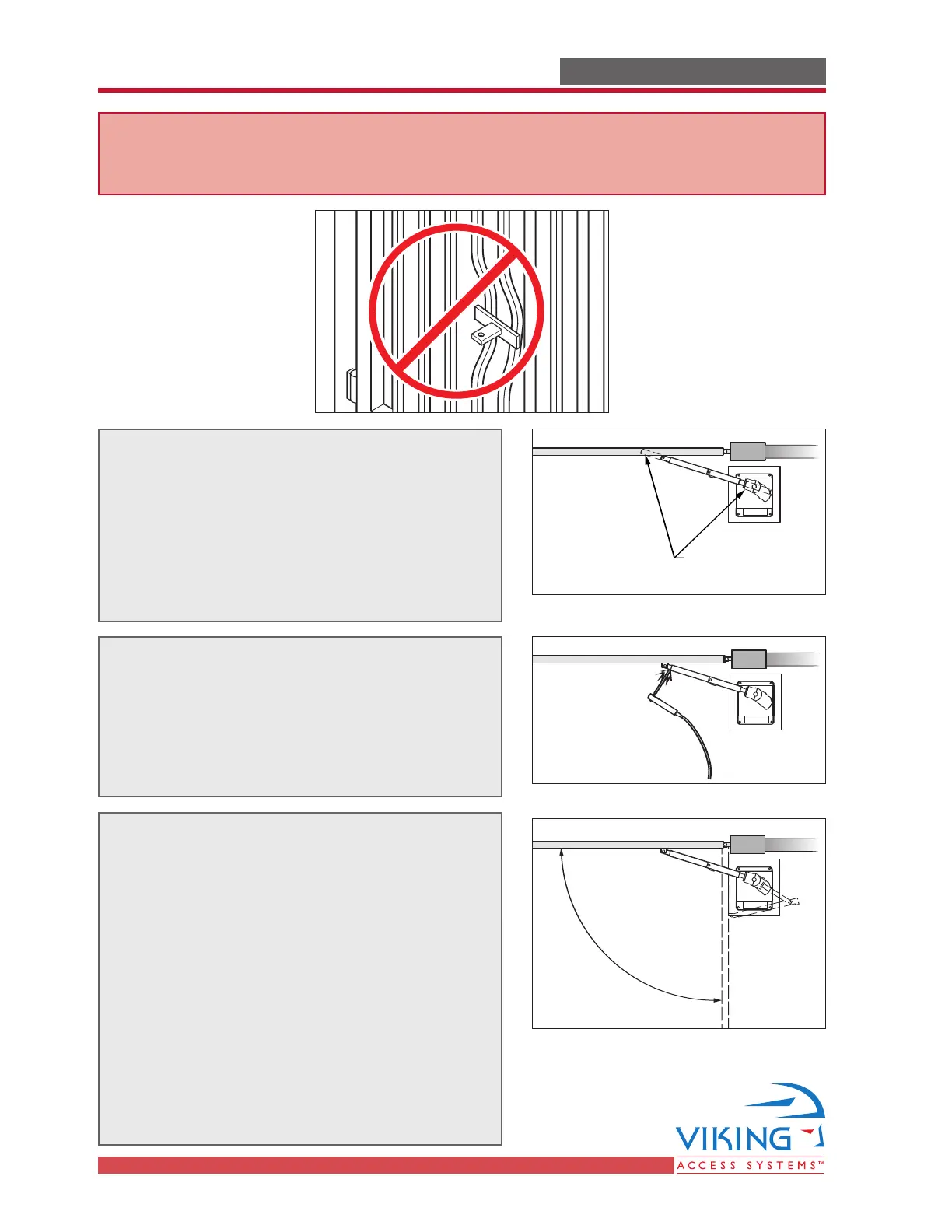
STEP 1
Release the clutch (see page 7). Cut the
extension arms according to the desired plan
of installation (Figure A on page 10).
Note: Leave some additional material when
cutting the extension arms to allow for
additional adjustment.
STEP 2
Position the pieces of the articulated arm
with the gate in the closed position. Ensure
that the dimensions correspond to the chosen
plan of installation. Use C-clamps or tack-weld
pieces to aid in the pre-installation process.
Remove Excess
Extension Tube
STEP 3
With the clutch released, move the gate
manually from the completely open to the
completely closed position. Verify that:
a) The gate and arm combination can
provide the desired operation.
b) The arm does not bind in its movement,
especially in the open position.
Note: The total travel angle of the primary arm
on the output shaft determines the speed of the
gate operation. The smaller the travel angle,
the quicker the gate will open and close.
GATE OPERATOR INSTALLATIONGATE OPERATOR INSTALLATION
CAUTION - If mounting bar is not welded to a frame member that runs the full
length of the gate, the gate operator may damage the gate. Do not weld the bar
or backing plate to a few pickets.