TECHNICAL SUPPORT 1 800 908 0884
24
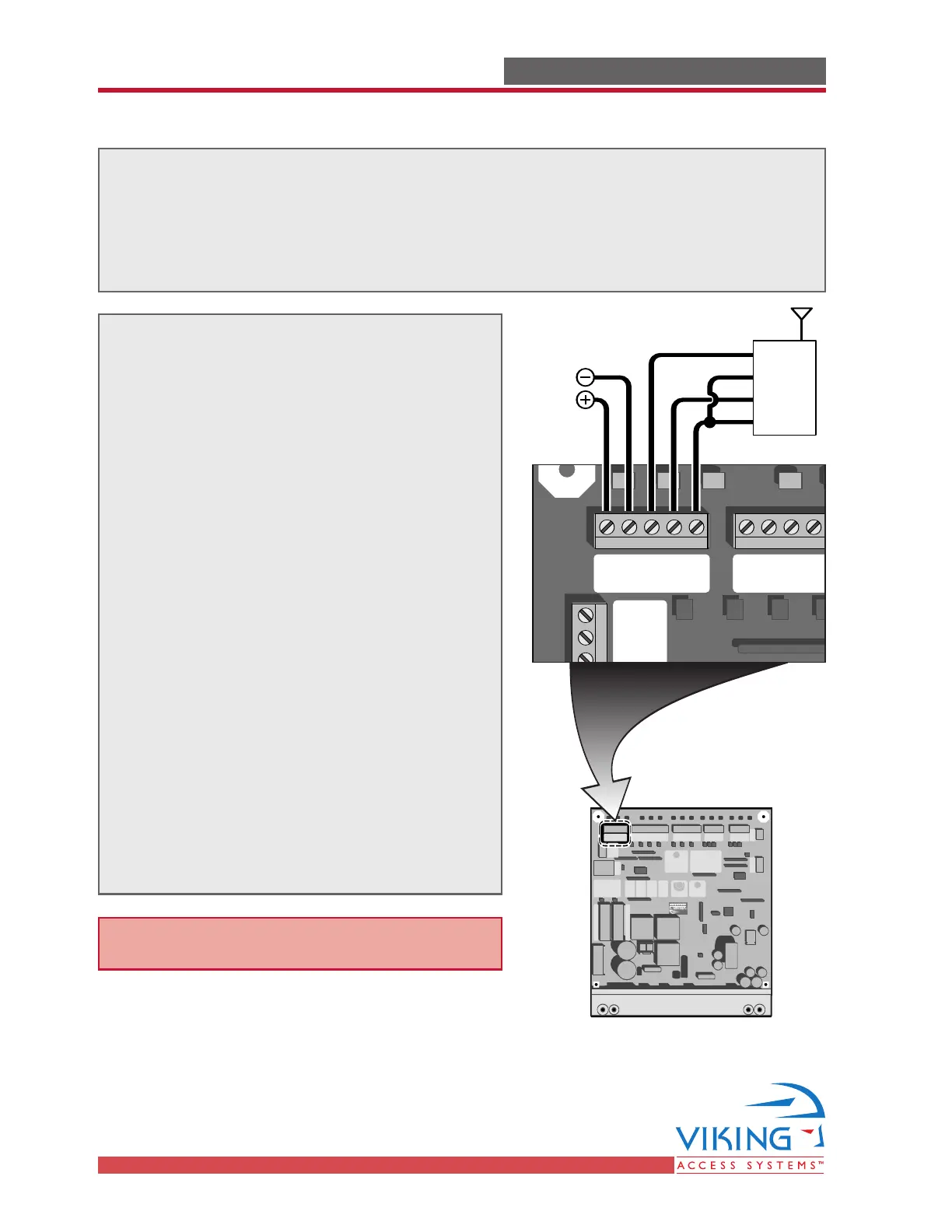
ACCESSORY CONNECTIONSACCESSORY CONNECTIONS
When connecting the Radio Receiver carefully verify the proper connections.
The maximum voltage that the control board provides for external accessories is the
maximum voltage of the battery, which is about 28 volts.
In the event of an electrical short the board will protect itself by shutting down and
will remain shut down until the short is corrected.
The control board provides two modes of
operation that a radio receiver can control
the gate:
Open-Stop-Close
1. By having the radio receiver connected as
illustrated and with the Hold Open Timer
OFF (see page 29):
Every command of the radio transmitter
will control the gate as follow:
a) First command opens the gate,
b) Second command stops the gate and
c) Third command closes the gate
d) Any subsequent commands will continue
in the same order to control the gate.
This type of configuration is not
recommended for a commercial
installations.
Open Only
2. By having the radio receiver connected as
illustrated and with the Hold Open Timer
ON (see page 29):
Each command of the radio transmitter is
ALWAYS AN OPEN COMMAND to the gate.
Radio Receiver
Radio Station
Mag.
Lock
Mag. Lock
Safety ConnectorOpen CommandsGuard StationMaster/Slave
Brake
UL
Siren
Radio
Rec.
UL
Sensor
OPEN RIGHT
OPEN LEFT
Safety
Loop
Center
Loop
Obstruction
Sensor
Charger
Power
Low Battery
Motor Sensor
Hold Open
Timer
Stop
Overlap Delay
Close Open
Obstruction
Sensor
min.MAX
Overlap Delay
1.5
0
3
Radio Station
Loop Connector Open Commands Guard Station
Master/Slave
GND
Close
Stop
Open
GND
Close
Stop
Open
Gnd
Fire
Gnd
Strike
Gnd
Exit
Gnd
Center
Gnd
Reopen
Gnd
UL
Gnd
+28v
Gnd
Radio
Gnd
+28v
+28v
Mag.
Lock
Fail Safe/Secure
Mag. Lock
N.C.
COM
N.O.
Charger
Power
Low Battery
Motor Sensor
Hold Open
Timer
Stop CloseOpen
LimitLimit
30sec
60secoff
1sec
Radio
Rec.
UL
Sensor
Safety
Loop
Center
Loop
Brake
UL
Siren
Obstruction
Sensor
min. MAX
Overlap
Delay
1.5
0
3
Mag.
Lock
Fail
Safe/Secure
Hold Open
Timer
Stop
Close
Open
30
60
Off
1
Radio
Rec.
UL
Sens
Safety
Loop
Center
Loop
Brake
Siren
External
Accessories
COM
NO
Gnd
+24VDC
Note: All controls are normally open.