SECTION TSM 344 ISSUE E PAGE 10 OF 24
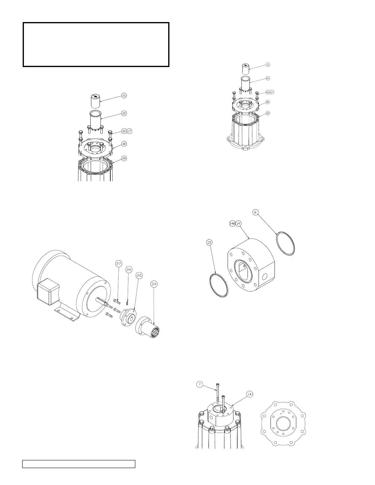
Remove the drive magnet assembly (item 24) from the
motor by loosening the setscrew (item 26) in the magnet
hub and slide off the motor shaft. Retain the key from
the motor shaft.
If required, the magnet hub (item 25) canister be
separated from the drive magnet (item 24) by removing
the four screws (item 27) and detaching.
Place the motor spool (item 20) flat on the work
surface. Align “molded-in” flats on the spool adapter
plate (item 18) with any two of the motor mounting bolt
holes on the motor spool as shown.
Set in place and install eight mounting bolts and washers
(items 16, 17). Tighten these bolts to the torque specified
on Always tighten fasteners in a progressive
“crisscross” pattern.
Install the containment canister (item 19) into the spool
adapter plate until it is properly seated into the assembly.
Inspect all O-Rings to be sure there is no damage such
as pinching prior to assembly.
Install O-Rings (items 6, 15) into grooves on both sides
of the center housing. Some O-Ring lubricant may help
keep the O-Rings in place during assembly. Be sure
both O-Rings are fully seated into housing grooves.
Place the center housing (item 14) with O-Rings installed
onto the spool adapter plate (open bore facing out),
aligning the flat sides on the center housing to the flat
sides on the spool adapter plate as shown. If the center
housing does not sit flat, rotate 180º until it seats into
place.
Secure the center housing using 2 bolts (item 7) in holes
as shown. Tighten these bolts to the torque specified
on Always tighten fasteners in a progressive
“crisscross” pattern.
Refer to for details.
Remove the driven magnet assembly (item 21) and
containment canister (item 19) from the adapter plate
as shown.
Inspect and remove any debris or foreign materials that
may have attached to the magnet.
Install the driven magnet assembly (item 21) into the
containment canister. The driven magnet is symmetrical
and can be inserted with either end facing out (orientation
does not matter).