SECTION TSM 344 ISSUE E PAGE 18 OF 24
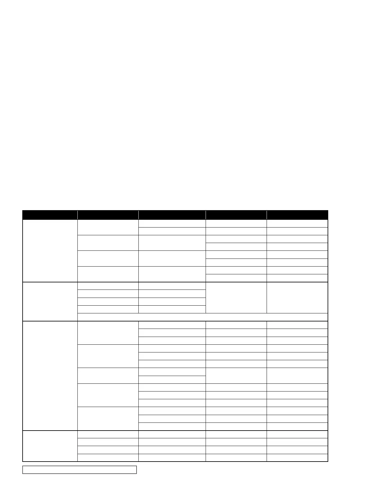
Bearings
E02
ID 0.293” 0.0025 bore wear 0.005 bore wear
Length 0.499” end wear – flip over both ends worn
E05 and E12 ID 0.439”
0.003 bore wear 0.006 bore wear
end wear – flip over both ends worn
E25 ID 0.627”
0.004 bore wear 0.008 bore wear
end wear – flip over both ends worn
E75 and E125 ID 1.002”
0.005 bore wear 0.010 bore wear
end wear – flip over both ends worn
Shafts
E02 OD 0.2916”
0.001 smooth wear
0.001 deep or rough
scoring
E05 and E12 OD 0.437”
E25 OD 0.625”
E75 and E125 OD 1.000”
no cracks or chips in shaft surface are allowed
Gears
E02
Length 0.4055” 0.0005 wear – length 0.001 wear – length
OD 0.600” 0.003 wear – OD 0.006 wear – OD
0.010 Backlash 0.020 Backlash
E05
Length 0.624” 0.001 wear – length 0.002 wear – length
OD 1.063” 0.004 wear – OD 0.008 wear – OD
0.015 Backlash 0.030 Backlash
E12
Length 1.249”
Same as E05 above Same as E05 above
OD 1.063”
E25
Length 1.499” 0.002 wear – length 0.004 wear – length
OD 1.417” 0.005 wear – OD 0.010 wear – OD
0.020 Backlash 0.040 Backlash
E75 and E125
Length 1.998” 0.003 wear – length 0.006 wear – length
OD 2.125” 0.006 wear – OD 0.012 wear – OD
0.025 Backlash 0.050 Backlash
Housing Liner
E02 n/a 0.002 wear or step 0.004 wear or step
E05 and E12 n/a 0.003 wear or step 0.006 wear or step
E25 n/a 0.004 wear or step 0.008 wear or step
E75 and E125 n/a 0.005 wear or step 0.010 wear or step
Inspect internal pump components as follows:
Inspect bearing bores (2) and end surfaces for wear and
scoring. If wear or scoring is present on the end surface
of the bearing, the bearing can be flipped to expose the
undamaged face to the gear side. Bearing should be
replaced when both ends show wear and/or scoring, or when
the bores have reached the replacement limit (see chart).
Both the idler and the drive shaft should be inspected
carefully for scoring, wear, and any signs of cracking or chips
in the surface of the ceramic material. No cracks or chips
are allowed. Shafts should be replaced if they show signs of
cracks or chips anywhere on the surface, if they are deeply
scored, or if they have reached their replacement limit (see
chart).
Gears can be measured for dimensional change to their
length and outside diameter. Gear teeth should also be
visually inspected for wear and damage. Gear teeth can
be damaged due to solids moving through the pump, which
will affect only some teeth, or excessive pressure, which
will distort the outside tips of all teeth. Gears that have
reached their replacement limits (see chart) or show signs of
physical damage or distortion should be replaced. Backlash
can be checked by temporarily inserting the two gear/shaft
assemblies into known good bearings and observing gear
tooth mesh and backlash.
The housing liner should be visually inspected for scoring,
wear, and steps on the ID of the two gear bores. See chart
for specific limits.
The viscosity of the pumped product will affect the service
limits of your CMD pump. Fluids with higher viscosities will
usually be more tolerant of wear and allow longer maintenance
intervals. Fluids with low viscosities will usually require more
frequent maintenance, as they are less tolerant of clearances
between the pump’s internal surfaces. Each application is
different, and only regular inspection and good records will
determine what the correct maintenance interval is for your
application.