SECTION TSM 344 ISSUE E PAGE 17 OF 24
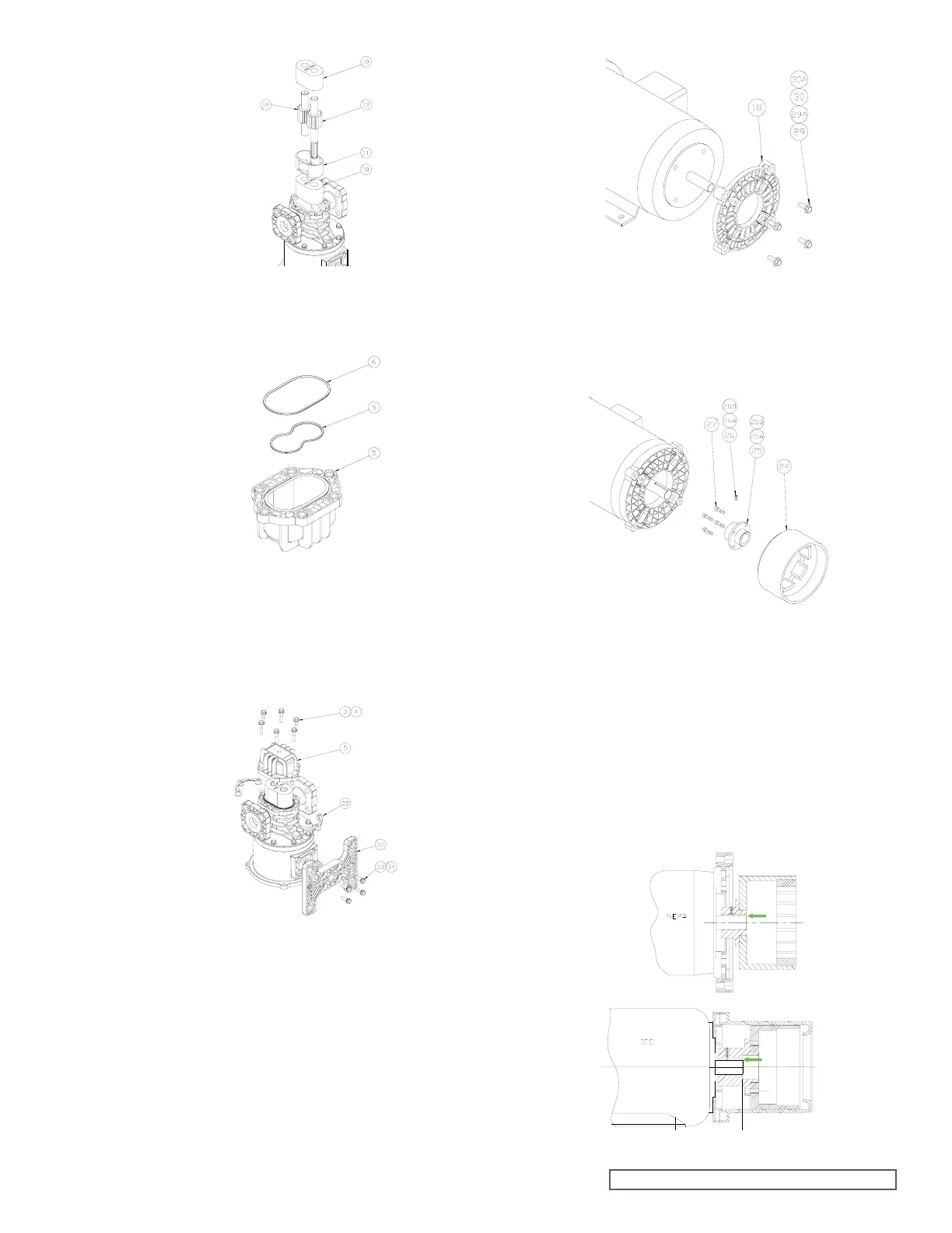
Install the two O-Rings (items 6, 9) into the front cover
(item 5) as shown. Some O-Ring lubricant may help
keep the O-Rings in place during assembly.
Place the front cover (item 5) with O-Ring onto the
assembled pump. Secure the front cover using the
six bolts and washers (items 3, 4) and two nut plates
(item 28) as shown. The flat side of the nut plates mate
against the back of the center housing flange. Tighten
bolts to the torque specified on Always tighten
fasteners in a progressive “crisscross” pattern.
Align the keyway, and slide the drive magnet onto the
motor shaft until the end of the motor shaft aligns with
faces of the drive magnet motor hub as shown below.
Secure with the setscrew (item 26). Application of a no-
seize compound on the shaft and key will make future
maintenance easier.
Complete the assembly by replacing the assembled
pump onto the motor, using care not to allow fingers
to get pinched when the magnets attract. Secure the
pump to the motor with the four bolts and washers
(items 22, 23). Always tighten fasteners in a progressive
“crisscross” pattern.
Inspect and remove any debris or foreign materials that
may have attached to the magnet.
Secure the magnet hub (item 25) to the drive magnet
(item 24) using the four screws (item 27). Always tighten
fasteners in a progressive “crisscross” pattern.
Secure the mounting base (item 32) to the motor spool
(item 20) using the four bolts and washers (items 33,
34) as shown. Always tighten fasteners in a progressive
“crisscross” pattern.
If it was removed, install the motor adaptor plate
(item 18) onto the motor face using the four bolts and
washers (items 29 and 30). Always tighten fasteners in a
progressive “crisscross” pattern.