SECTION TSM 344 ISSUE E PAGE 16 OF 24
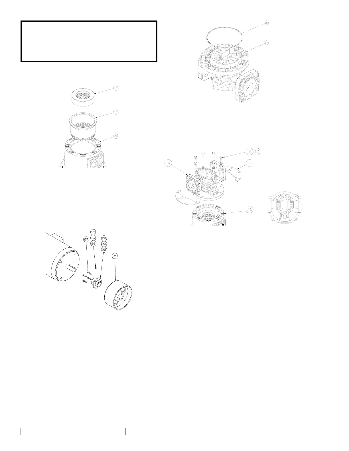
Place the center housing (item 14) onto the motor spool,
aligning the port connections with the pump baseplate as
shown. Place the two retaining plates (item 35) onto the
center housing and secure with eight bolts and washers
(items 16, 17). Tighten bolts to the torque specified
on Always tighten fasteners in a progressive
“crisscross” pattern.
Insert a bearing (item 10) into center housing (item 14)
and slide to bottom of bore. Bearings are symmetrical
and orientation does not matter. Install the housing liner
(item 11) and slide until it seats against the first bearing.
Install idler gear (item 12) into the top hole in the bearing
until the gear seats against the first bearing.
Install the drive gear (item 13), splined-end first, into the
assembly until it bottoms out against the bearing. The
shaft may have to be rotated slightly to properly fit the
splined-end into the drive magnet and mesh gear teeth
with the idler gear.
Insert the second bearing into the housing bore until it
rests against the housing liner. Bearings are symmetrical
and orientation does not matter.
Remove drive magnet assembly from the motor by
loosening the setscrew (item 26) in the magnet hub (item
25) and slide off the motor shaft. Retain the key from the
motor shaft.
If required, the magnet hub (item 25) can be separated
from the drive magnet (item 24) by removing the four
screws (item 27) and detaching.
Place the motor spool flat on the work surface.
Insert containment canister (item 19) and driven magnet
(item 21) into motor spool (item 20) as shown. The
driven magnet is symmetrical and orientation does not
matter.
Inspect all O-Rings to be sure there is no damage such
as pinching prior to assembly.
Install O-Ring (item 15) into the back side of the center
housing (item 14) as shown. Some O-Ring lubricant
may help keep the O-Rings in place during assembly.
Be sure the O-Ring is fully seated into housing groove.
Refer to for details.
Remove driven magnet assembly (item 21) and
containment canister (item 19) from the motor spool
(item 20) as shown.