© 2011 Viking Preferred Service
26
Service Diagnostics and Procedures
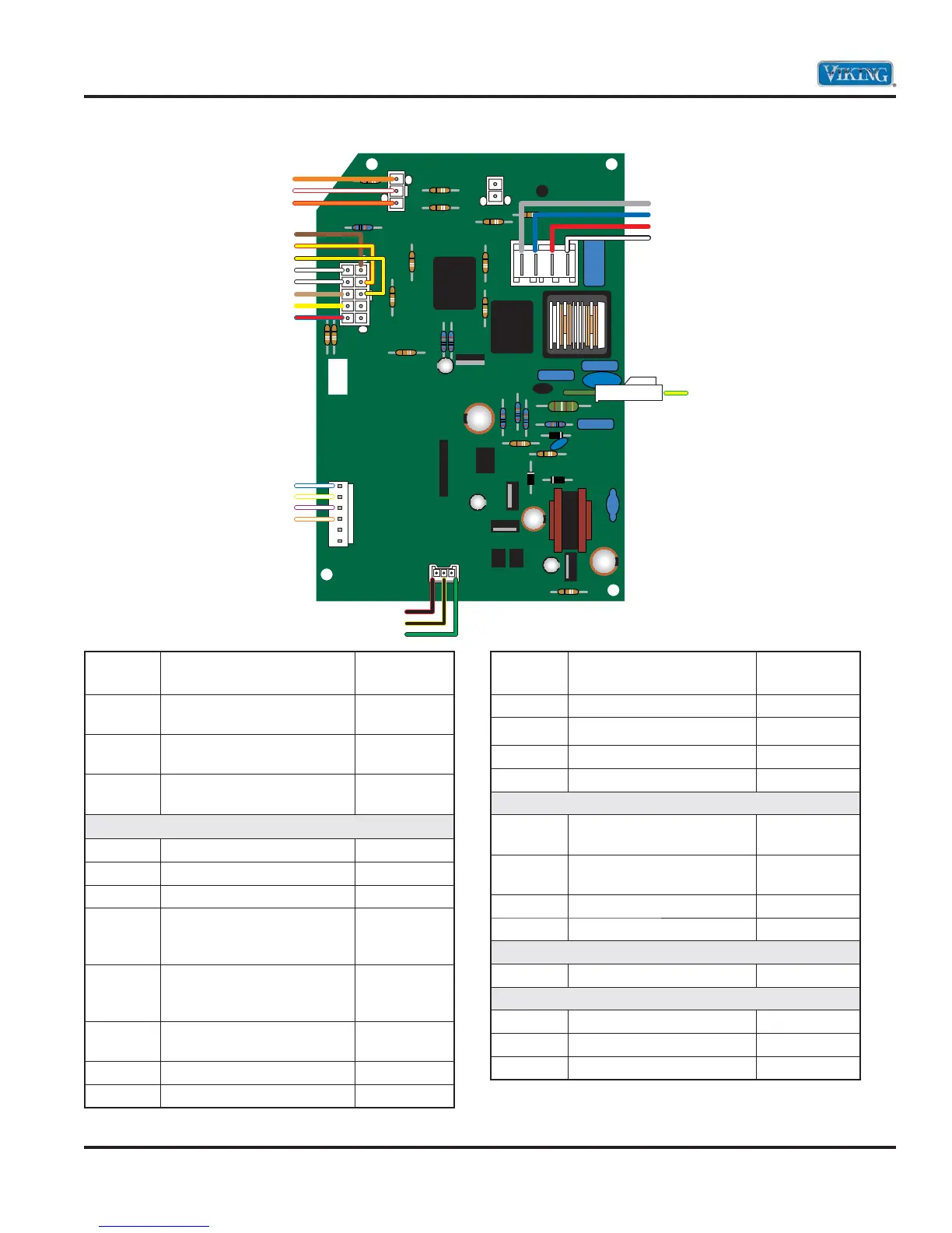
Main Control Board Wiring Connections
Pin
Number Description Wire Color
CN6-3 Defrost Terminator and
Defrost Heater
Orange
CN6-2 Refrigerator Light Switch
and Refrigerator Light
Red/White
CN6-1 Freezer Light Switch and
Freezer Light
Red/Orange
CN2-10 Line Defrost Terminator Brown
CN2-9 Line Damper Motor Yellow/Red
CN2-8 Line Evaporator Fan Yellow/Black
CN2-5 Neutral Damper Motor,
Evaporator Fan, and
Defrost Heater
White/Black
CN2-4 Neutral Damper Motor,
Evaporator Fan, and
Defrost Heater
White/Black
CN2-3 Neutral Ice Maker and
Solenoid
Tan
CN2-2 Neutral Water Valve Yellow
CN2-1 Damper Motor NC Blue/Red
Pin
Number Description Wire Color
CH3-1 Refrigerator Thermistor White/Blue
CH3-2 Freezer Thermistor White/Yellow
CH3-3 Ambient Thermistor White/Violet
CH3-4 Thermistor Ground White/Orange
CN1-4 Neutral PTC Relay and
Condenser Motor
Gray
CN1-3 Line Overload and
Condenser Motor
Blue
CN1-2 Line Power Cord Red
CN1-1 Neutral Power Cord White
P1 Compound Ground Green/Yellow
CN4B-1 +14 VDC Display PCB Red/Black
CN4B-2 Neutral Display PCB Yellow/Black
CN4B-3 Ground Display PCB Black/Green
CH3-1
CH3-2
CH3-3
CH3-4
CN6-3
CN6-2
CN6-1
CN2-10
CN2-9
CN2-8
CN2-5
CN2-4
CN2-3
CN2-2
CN2-1
CN4B-1
CN4B-2
CN4B-3
P-1
CN1-4
CN1-3
CN1-2
CN1-1