WARNING - Not following these instructions may cause severe injury or death to persons.
IMPORTANT SAFETY INFORMATIONIMPORTANT SAFETY INFORMATION
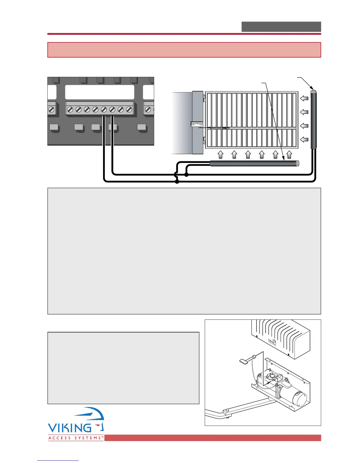
Edge Sensor (contact sensor) Installation
Edge sensor or like must be installed to reduce the risk of entrapment.
Use only UL325 compliance devices like:Use only UL325 compliance devices like:
Miller Edge 3-sided activation for an added measure of protection MGR20 or MGS20
If you install another device:
a) Ensure its compliance with UL325,
b) Use the recommended supply voltage,
c) Follow the installation guidelines of the device.
One or more contact sensors shall be located on the inside and outside leading edge
of a swing gate. Additionally, if the bottom edge of a swing gate is greater than 6
inches (152 mm) above the ground at any point in its arc of travel, one or more
contact sensors shall be located on the bottom edge.
Consult the installation manual for the UL325 device (photo beam or like) for detail
information about the usage, installation and maintenance.
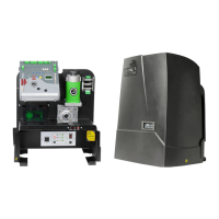
Manual Release
When manual operation is required:
Remove the cover, locate the chained key and
turn the key to push the locking-pin down.
At end of operations, lock the geared motor again
by releasing locking-pin.
Attention: Lock and release operations MUST
be performed with motor NOT RUNNING.