7602030
26
FIG.27
FIG.26
a
a
b
d
b
d
b
c
a
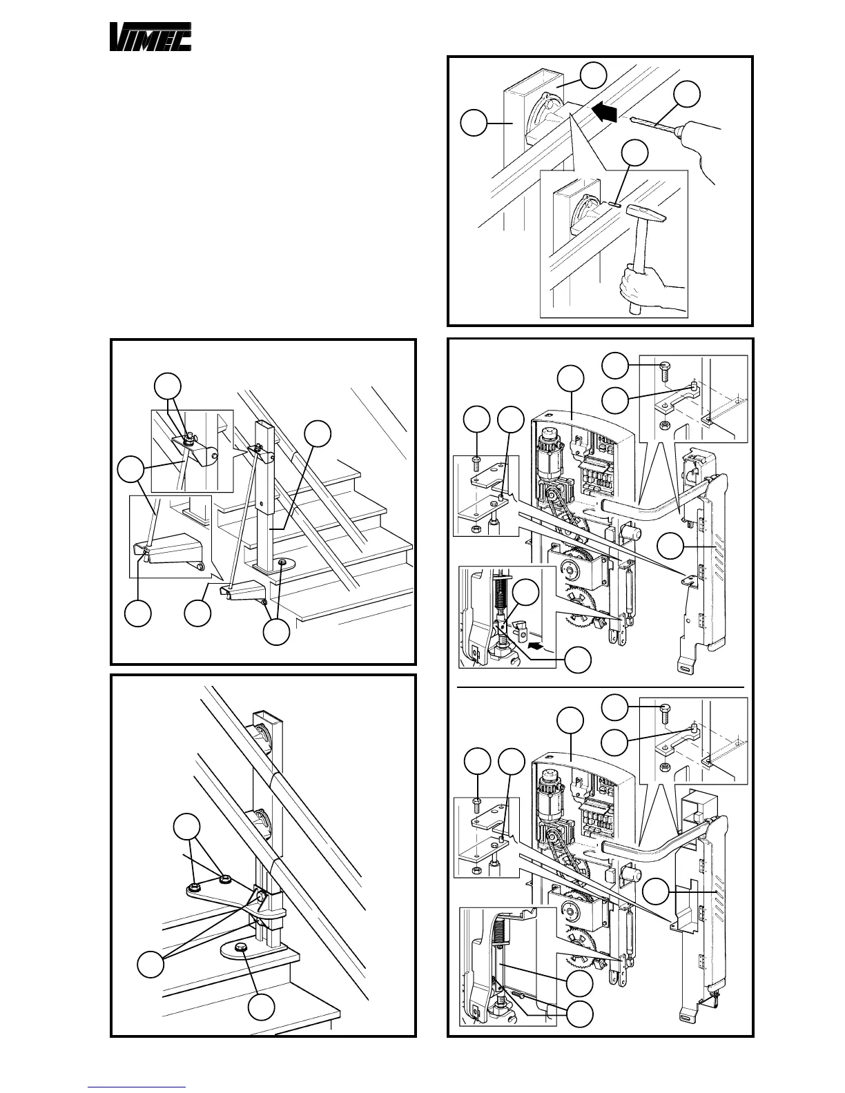
8) BARS ASSEMBLY
Mount the bars supports (Fig. 29/b) on the machine fra-
me (Fig. 29/a) making the corresponding reference pins
(Fig. 29/c) match.
Tighten the bars with the proper issued screws (Fig.
29/d).
Then, proceed to connection of the electrical card
sheaths.
8.1) Indipendent bars - Connected bars
Connect the cable in the lower part of the bar (Fig. 29/e)
with the footboard interblock system (Fig. 29/f).
8.2) Retractile bars
Connect the lever in the lower part of the bar (Fig. 29/g)
with the screw and the self-locking nut (Fig. 29/h).
FIG.28
c
a
b
d
FIG.29
d
a
b
d
c
f
e
d
a
b
g
h
d
c
c
c