7602030
24
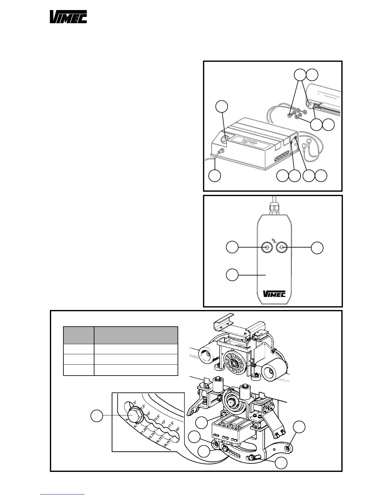
Once the guide assembly is through, for machine with
costant gradient lower than 20°, check the slant of the
whole guide (maximum allowed error 1°) before sarting
the machine up (see Fig. 20).
5) POWER SUPPLY UNIT CONNECTION
- Connect the cables (positive and negative) to the proper
terminal of the busway fixed to the guide (Fig. 21/e -
Fig. 21/f).
- Connect the electric power 230 V 50 Hz to the suitable
socket (Fig. 21/c).
- At the end of installation, give tension through the main
switch (Fig. 21/d).
6) INSTALLER PUSHBUTTON CONNECTION
- Connect through suitable connection socket the in-
staller pushbutton (Fig. 22/a) (require it to Vimec service
department, as it is not supplied).
- By means of the (Fig. 22/b - Fig. 22/c) previously de-
scribed pushbutton panel controls take the structure
complete with trolley on the selected floor to continue
the assembly operations with total safety.
- Insert the spacing gauge (Fig. 23/g) between the guides
and assemble the connection/foot (Fig. 23/a).
- After having correctly spaced the guides (Fig. 23/b -
Fig. 23/c) with the spacing gauge (Fig. 23/g) and after
having perfectly placed in vertical position the connection
(Fig. 23/a), tighten the screws hard (Fig. 23/e and Fig.
23/f).
NOTE: Lift the machine up to the 1
st
rigid connection, if
the machine is not horizontal, screw in the screw M10x30
(Fig. 15/a) with washer (Fig. 15/b) in the clutch unit in
order to clear the upper swaying trolley from the clutch
unit.
The correct space is obtained when the clutch unit is
about 2 mm clear from the swaying trolley (Fig. 15/c).
FIG.21
c
-e
+f
d
-
a b
+
FIG.22
c
b
a
- Raise the machine a bit, in order to reset it.
- Slack the screw (Fig. 15/a) and its washer (Fig. 15/b)
to couple back the clutch unit with the swaying trolley.
FIG.20
2
1
2
3
3
POS.
DRIVING TORQUE
(daN x m)
1
2
3
2,5
6,0
4,5
3