7602030
25
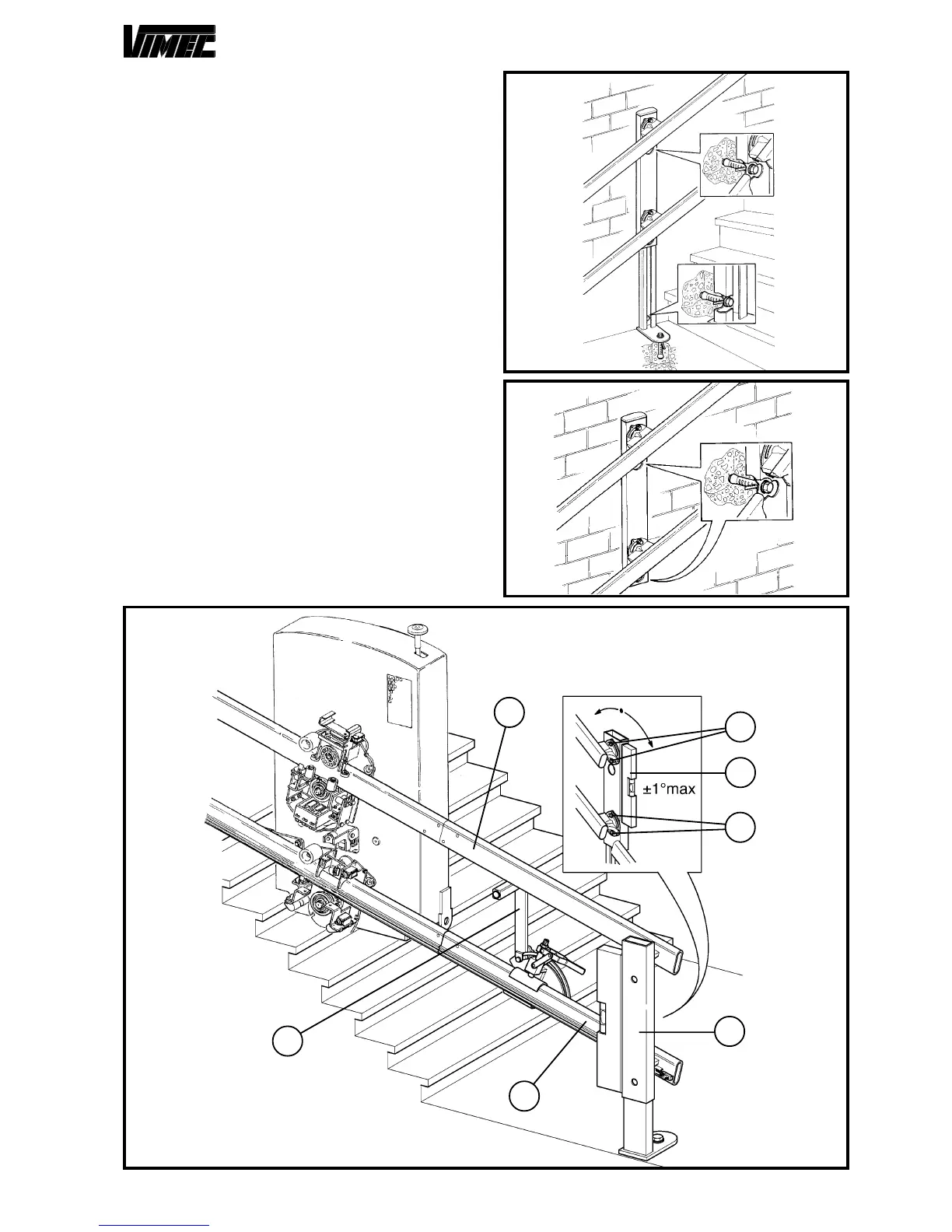
7) CONNECTION FEET FINAL ASSEMBLY
After having done a test operation to make sure that
everything has been correctly assembled, it is necessary
to fix the support feet to the ground and the connections
(where possible) to the wall.
According to the type of foot foreseen in the assembly
diagram, fix it hard as shown in the following examples
(Fig. 24-25-26-27).
In case of step-fixing foot (Fig. 27), drill the same steps
and block it all with the issued screws (Fig. 27/a).
After the fixing operation, tighten the screws hard (Fig.
27/b).
In case of flag-support foot (Fig. 26), drill in the fixing
points and block it all with the issued screws (Fig. 26/
a).
Tension the foot (Fig. 26/c) introducing the threaded bar
in the proper holes (Fig. 26/b) and screwing in the nut
and the counternut (Fig. 26/d) up to reaching of the
tensioning.
To avoid guide inclination changings (Fig. 28/a) in the
future, it is necessary to drill a hole (Fig. 28/b) on the
connection joint (Fig. 28/c), after having furthuerly
checked the correct assembly, and then insert a blocking
peg (Fig. 28/d) in that same hole.
FIG.24
FIG.25
FIG.23
c
g
b
a
f
d
e
 Loading...