7602030
22
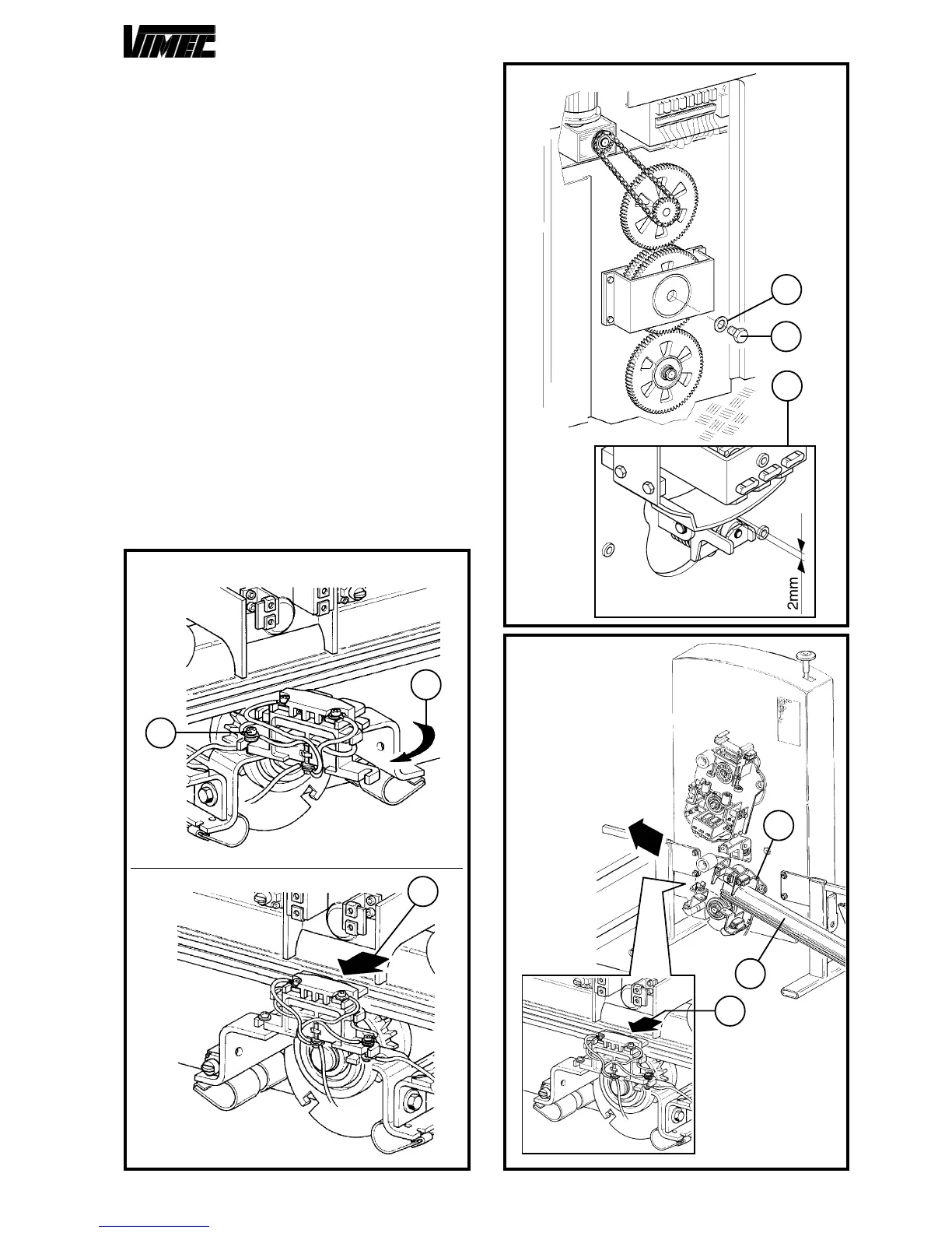
4) TROLLEY ASSEMBLY
- Position the structure kitted with trolleys in the parking
zone at low plan.
- Completely fasten the screw M10x30 (Fig. 15/a) with
washer (Fig. 15/b) on the friction block in order to re-
lease the upper platform balance from the friction group;
the correct space is obtained when the clutch group is
about 2 mm clear from the swaying trolley (Fig. 15/c).
- Loosen the brush-holder fastening screw (Fig. 14/a)
and rotate it as indicated by the arrow (Fig. 14/b) or
pull the brushes backwords (Fig. 14/c) during the
introduction of the tube in the lower trolley.
NOTE: During the stages described as follows, pay much
attention to the correcto positioning of the slides (Fig.
17/f - 18/e) after having lubricated them with grease.
- Insert the lower tube (Fig. 16/a) in the lower swaying
trolley (Fig. 16/b) remembering, if they have not been
slewed (Fig. 14/b), to draw back the brushes (Fig. 14/c).
- Insert the lower tube (Fig. 17/a) in the swaying trolley
(Fig. 17/b) making sure that the teeth of the dragging
pinion (Fig. 17/e) correctly match with the holes, until
carrying out the junction of the guide with the one formerly
prearranged (Fig. 17/c).
- Carry out the junction of the busway (Fig. 17/d) as
previously described.
FIG.16
FIG.14
FIG.15
a
b
a
b
c
b
SOLUTION "A"
SOLUTION "B"
c
a
c
 Loading...