7602030
35
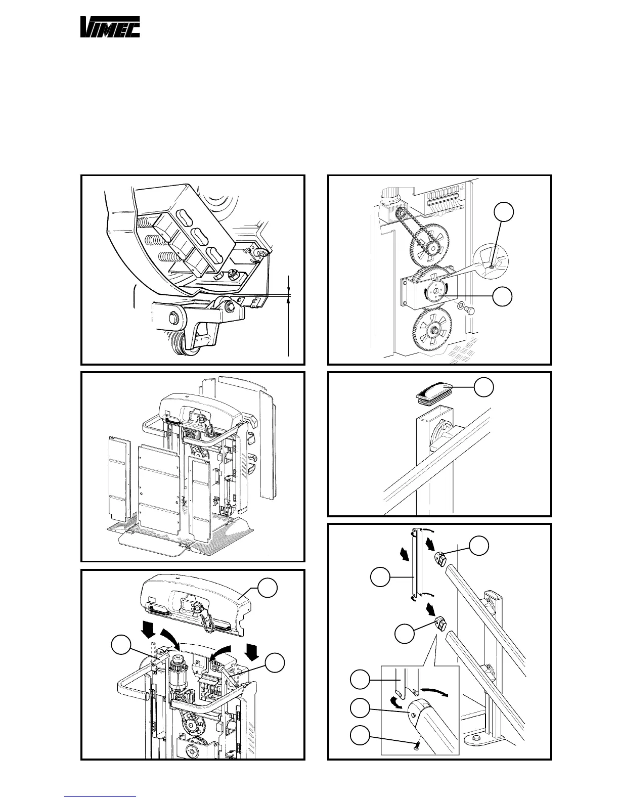
FIG.52
FIG.53
0,5÷1,5 mm
19) FITTING THE BODYWORK SECTIONS (Fig. 53-54)
Firmly assembly the dome (Fig. 54/b), removing the support
feet (Fig. 54/a). After having rotated these latter towards
the inside, fix the dome to the machine using the proper
screws formerly used to fix it to the support plates (Fig.
54/a).
Fit all the bodywork sections as on the overall drawing
supplied with the machine, paying attention not to crush
any electric cables or working components.
20) TERMINALS AND PLUG ASSEMBLY
- Mount by pressure the proper issued plugs (56/a) on
each guides connection.
- Mount the proper connection profiles (Fig. 57/a) on the
guides upper and lower terminal sections. To carry out
such assembly it only takes introducing the end plugs
(Fig. 57/b) in the guides and lock them with the screws
(Fig. 57/c) issued.
- Eventually, mount the connection profile (Fig. 57/a) by
pressure as shown in Fig. 57.
FIG.54
b
a
FIG.55
FIG.56
FIG.57
b
a
a
a
c
b
a
b
a
b
 Loading...