7602030
21
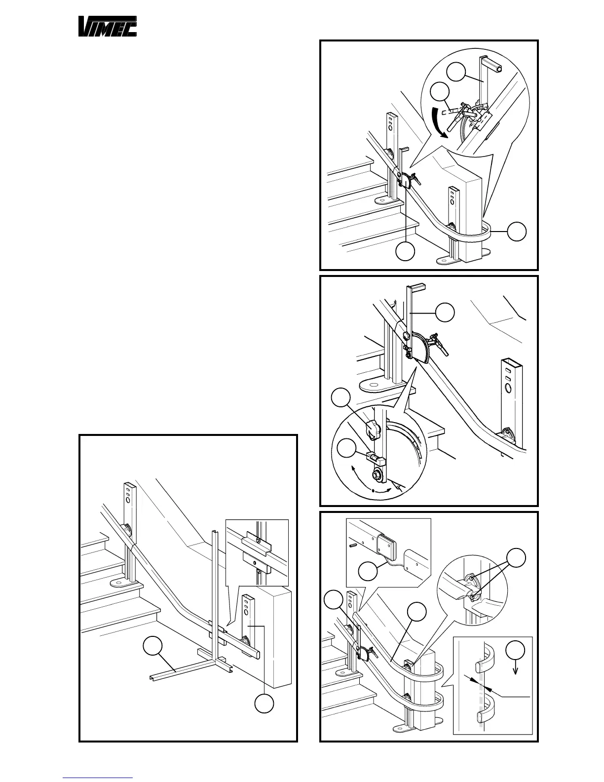
In order to facilitate the assembly operation for the wall
fastening (Fig. 10/a), it is advisable using the special
test feet (Fig. 10/b) (ask the Vimec service department,
as they are not supplied) to insert on the guide instead
of the middle fastenings (almost 1-2 every ramp).
NOTE: Before carrying out any machine handling test,
the connection (Fig. 10/a) must be fixed to the wall.
3) INSTALLING THE UPPER RAIL
- Position the spacing gauges (Fig. 11/a) (ask the Vimec
service department, as they are not supplied), on the
extreme edges of the first positioned guide section (Fig.
11/b) (curve) and block them hard rotating the lever as
shown in figure (Fig. 11/c).
- By loosening the handwheel (Fig. 12/a) and using a
spirit level (Fig. 12/b), position the support arm (Fig.
12/c) in perfectly vertical position. Once the adjustment
has been done, tighten the handwheel hard (Fig. 12/a).
- Position the upper guide (Fig. 13/a) on the spacing
gauges (Fig. 13/b) formerly positioned, and after having
checked the correct vertical sense (Fig. 13/c),
tighten the screews (Fig. 13/d) hard.
CAUTION: The couple securing the guide fixing
screws (Fig. 13/d) must be 6-7 daNm.
- Carry out the assembly of all the guide sections remained,
proceeding in sequence as formerly described down to
the bottom of the scale except the last one. If included
in the kit, insert the cable for push-button panles (Fig.
12/e) during the guides connection.
- When finished the assembly, retouch guides with sup-
plied black paint and seal the screws (Fig. 9/g) and the
nuts (Fig. 9/h) of the busway junction.
FIG.10
FIG.11
FIG.13
FIG.12
a
c
a
b
c
a
b
b
a
0±1
mm
e
d
a
b
c
 Loading...