7602030
20
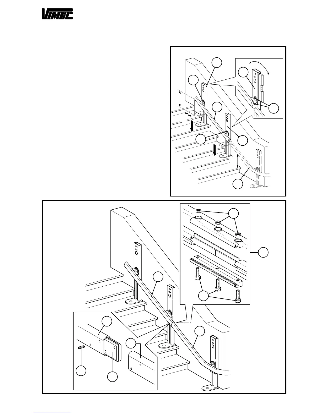
160 mm (Fig. 6/b) clear from the handrail of the separating
wall.
- Put the curve connection devices in vertical position (Fig.
7), tightening both securing screw (Fig. 7/a) at the end of
the adjustment.
CAUTION: The couple for the tightening of the gui-
de securing screws (Fig. 7/a) must be 6-7 daNm.
- Using the proper assembly punching (Fig. 3/b), locate
the guide section with feet (Fig. 8/a) to position right
above the formerly positioned curve (Fig. 8/b).
- Position the guide in the installation point (Fig. 8/a),
taking as reference the values in the assembly diagram
(example see Fig. 5) slide-off the feet and lightly tighten
just one nut (Fig. 8/c) of each connection device (Fig.
8/d).
- Insert in the upper guide tube (Fig. 9/a) the joint plates
(Fig. 9/e), screw without tightening the first 2 grub
screws.(Fig. 9/f).
- Draw near the low guide section (Fig. 9/b), assemble
the remaining grub screws and tighten them with a 8-9
daNm couple after verifying the correct tubes alignment
and the lack of space between one tube and the other.
Assemble the bus-way joint as shown in figure (Fig. 9/
d) after verifying the components cleanliness.
- As already done for the curve, set the connection
devices in perfectly vertical position (Fig. 8/e), tightening
both securing screws (Fig. 8/f) at the end of the
adjustment.
- Carry out the installation of all guide sections except
the last one as formerly described down to the bottom
of the scale.
FIG.8
C
D
A
± 1°
max
e
f
d
a
b
c
d
c
FIG.9
h
g
d
c
c
e
b
f
a
 Loading...