7602030
33
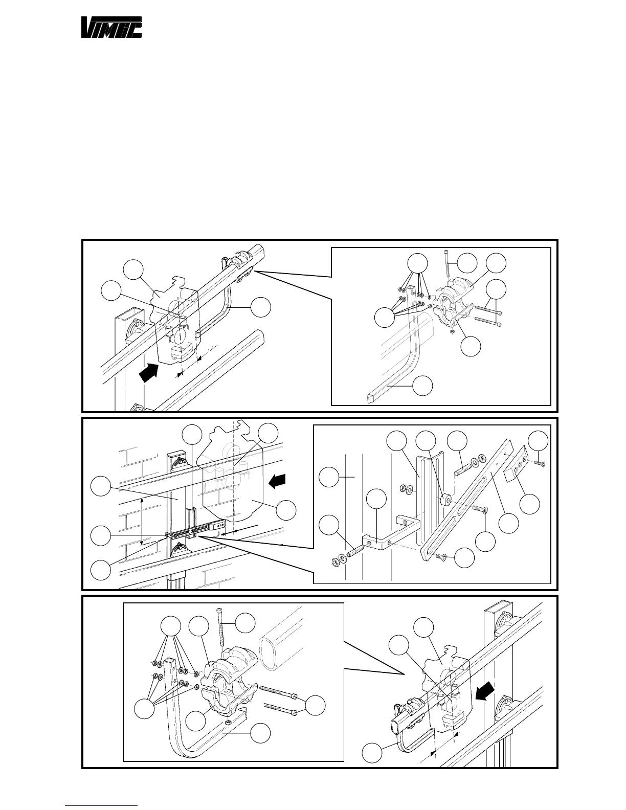
16) LIMIT STOP CAMS AND INTERMEDIATE STOP
ASSEMBLY
- Bring the stairlift to the stop position (Fig. 46/a - 47/a
- 48/a) tracing on the tube guide the centerline axis of
the machine (Fig. 46/b - 47/b - 48/b).
- Move the machine.
- In case of upper (Fig. 46/a) or lower (Fig. 48/a) stop,
assemble the proper limit switch cam (Fig. 46/e - 48/
e) using screws, nuts and washers (Fig. 46/c - 48/c)
and support (Fig. 46/d - 48/d) issued.
- Block the cam (Fig. 46/e - 48/e) on the guide at a 30
mm distance from the machine middle axis previously
traced.
- Eventually, secure all the screws.
- Nel caso di fermata intermedia (Fig. 47/a) assembly
the support (Fig. 47c) on the tubular (Fig. 47/d) by
means of two dowels M8x30 (Fig. 47/e).
Assembly the cam stiffening bracket (Fig. 47/f), the
spacer (Fig. 47/g), and the bracket cam fixing bracket
(Fig. 47/h) with screws TSPCE M8x16 (Fig. 47/n) and
TSPCE M8x35 (Fig. 47/i).
Assembly the cam (Fig. 47/l) with N°2 screws TSPCE
M5x20 (Fig. 47/m).
Place the cam at a distance of 177 mm from the lower
side of the upper guide tube, and at 30 mm from the
machine centerline axis traced before
(Fig. 47/b).
- Eventually, secure all the screws.
FIG.46
Upper limit stop cam
FIG.48
Lower limit stop cam
FIG.47
Intermediate stop cam
30
177
m
d
e
c
f g e
l
h
i
n
d
e
c
f
b
a
c d
c
d
c
c
e
c
e
d
c
c
c
d
a
b
e
30
30
a
b
e
 Loading...