7602030
27
9) ASSEMBLING THE PLATFORM WITH MOTORIZED
ACCESS FRONTAL (B.I. - B.C. - B.R.)
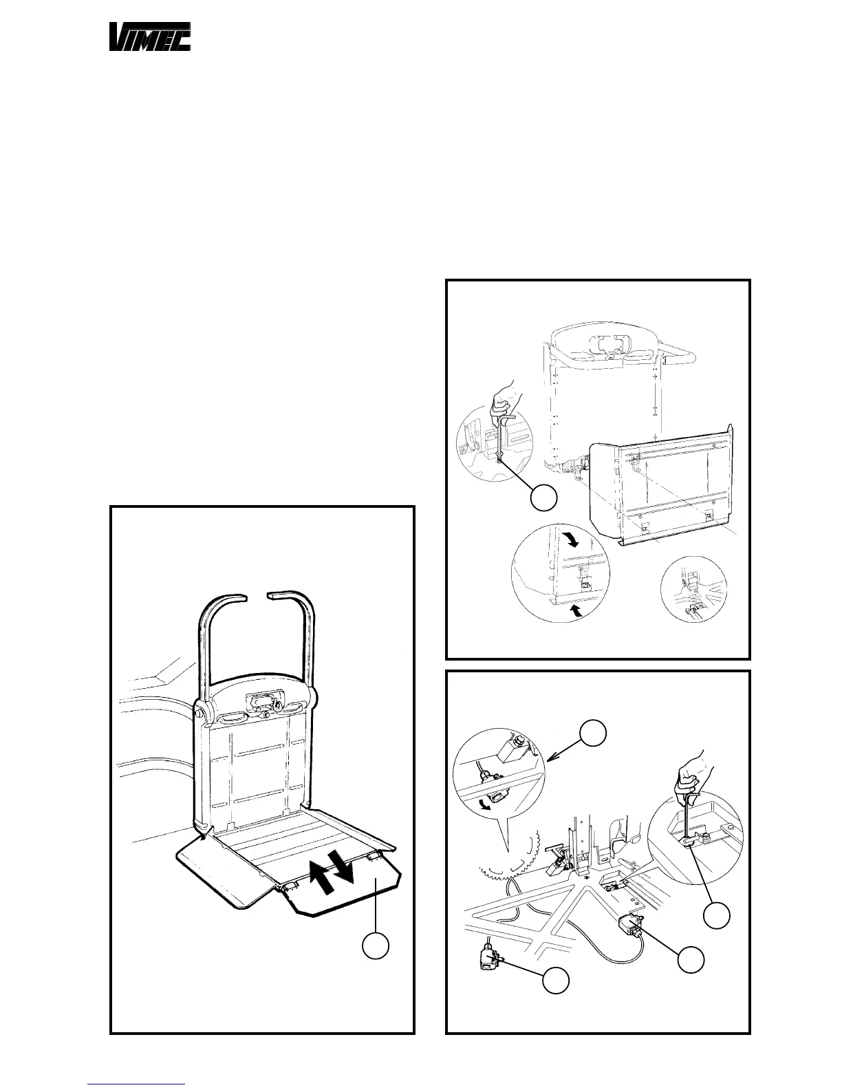
On customer request it is possible to have a footboard
with overturning front side (Fig. 30/a).
Such a footboard permits, on the lower floor only, to ac-
cess/go down perpendicularly to the machine.
9.1) Assembling the platform
a) Remove the top plate from the platform by undoing
the relative screws.
b) Make sure that the two platform supports, fixed by a
wedge and a plastic clamp, are in the assembly position
(Fig. 33/a/b).
c) Fit the platform, keeping it vertical and turning it
through 90° as shown in (Fig. 31).
d) Fix the platform to the frame using the relative M8
flathead screws (Fig. 31/a)
e) Fix the two microswitches of the sensor base (Fig.
32/a) to the platform, passing them between the sensor
base and the platform frame (Fig. 32/b).
If necessary, back off the sensor base tripping cams
(Fig. 32/c) to allow the microswitch to pass.
Then restore the original positions so that the sensor
base trips the microswitches when it is pressed.
FIG.30
a
FIG.31
a
c
b
a
FIG.32
a
f) Connect the lateral guard board operating cables (Fig.
34/f) and frontal (Fig. 34/e) to the fork (Fig. 34/b).
-
Tighten
with nut and screw.
- Insert the eccentric (Fig. 34/h) with handling belt (Fig.
34/g), front chute on the special pin (Fig. 34/i) and block
with seeger (Fig. 34/m).
B. R.: fix the cable (Fig. 34/f) already present on the
side bar chute with special screws.
- Fix the cable eye (Fig. 34/e) to the eccentric (Fig. 34/
h) by screw, nut and lock nut leaving the necessary
clearance for the rotation of the eye itself.