7602030
34
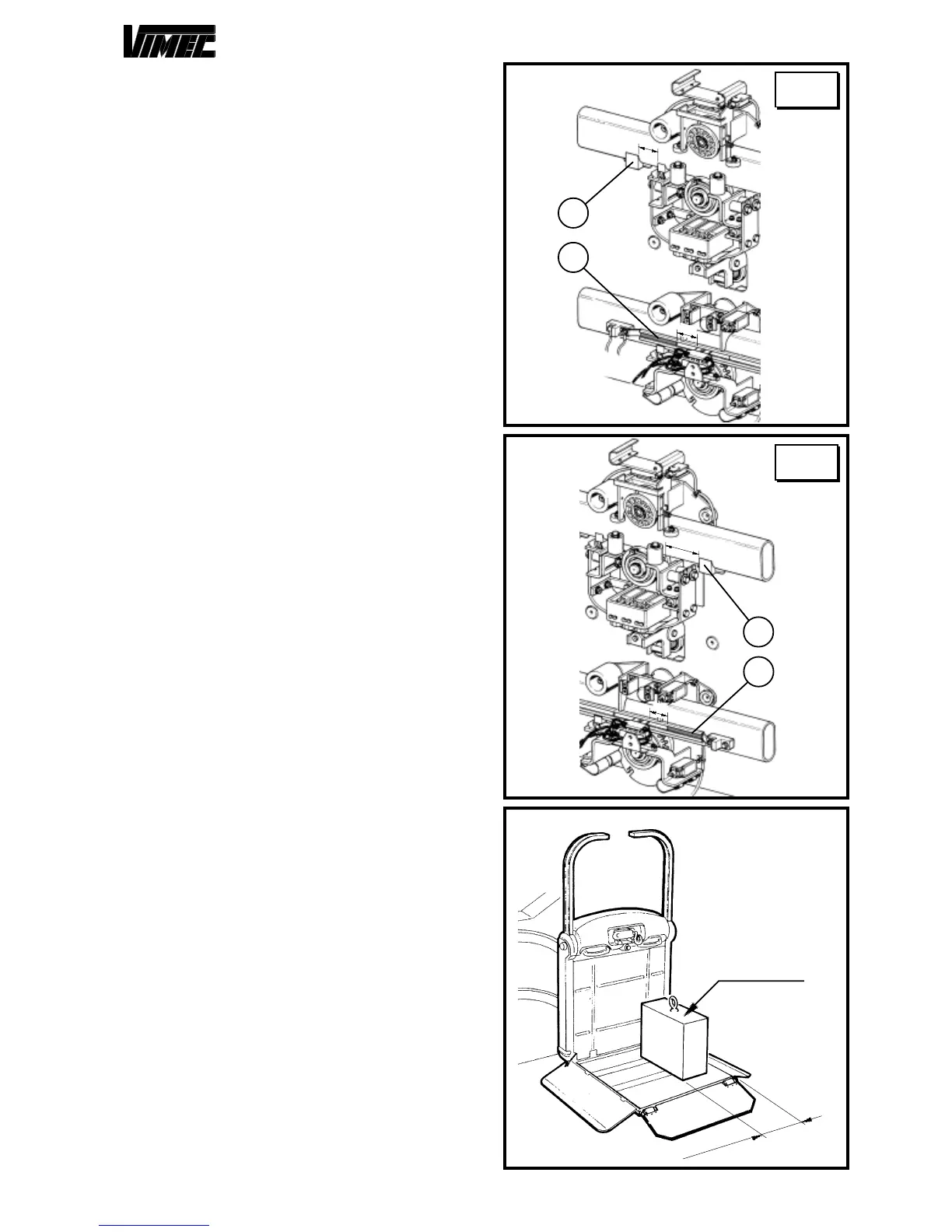
FIG.50
17) CAM PLACEMENT AND EXTRARUN
PLATES CHECK
Before executing the machine final test, it is necessary
to check the cams (Fig. 49/a-50/a) and extra-run dishes
(Fig. 49/b-50/b) correct placement both on the upper and
lower floor.
Such placement results as correct if the heights appear-
ing on the drawings are verified (see Fig. 49 and 50).
18) FINAL TESTING
Supply power to the system and perform the
following functional checks:
- Load test:
- Load the lift with 1.1 times the rated load stated on the
nameplate.
- Send the lift up and down several times, checking its
stability on the rail.
- Test for a machine with guide sections with
inclination lower than 20°
- Take the machine in the area superior to 25°, verify the
cam operation roll is 0,5÷1,5 mm far from the cam (see
Fig. 52).
-
In case it is necessary moving the roll closer to or
away from the cam the grub screw must be loosened
(Fig. 55/a) and the friction wheels hub must be turned
(Fig. 55/b). When the registration is made tighten the
grub screw (Fig. 55/a) with loctite.
- Then, take the machine in the area with inclination
lower than 20°, load a 250 kg weight with barycentre
150 mm far from the end (see Fig. 51).
- Verify the machine has not an inclination superior to
2°.
- Preliminary checks
- Perform the checks described in point 6.1 on page 8 of
the Use and Maintenance Manual.
- Safety gear test
- Test the safety gear as described in Section 9, point
“d".
- Verify foot-board, independent bars, retractile bars
interlock.
With the low side bar in stand-by position check that
the foot-board remains blocked whether it is in working
or in stand-by position.
For the motorized foot-board versions it is necessary to
carry out the same check taking care of releasing the
actuator foot-board by pressing the release button (Fig.
12/a - section "Operation and Maintenance").
- Check on fixing of the rail
- Check that the rail is positioned in accordance with the
dimensions stated in the installation drawing (or system
layout) supplied with the lift.
- Check that all the fixing screws of the connections to
the mounts or any expansion plugs are stable and firmly
tightened.
FIG.49
a
b
25
15
a
b
25
15
HIGH
LEVEL
LOW
LEVEL
FIG.51
150 mm
250 kg
 Loading...