7602030
23
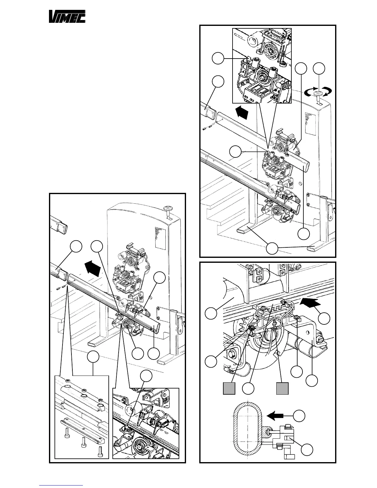
- Insert the upper tube (Fig. 18/a) in the swaying trolley
(Fig. 18/b) and, with the help of the upper handwheel,
(Fig. 18/c), insert it up to execution of the junction with
the tube (Fig. 18/d) previously prearranged.
- In case of former opening of the brush-holding group (Fig.
19), rotate it to the initial position.
- Manually press the unit (Fig. 19/c) in the direction indi-
cated by the arrow (Fig. 19/d) till making both the
brushes re-enter at least 5 mm.
- Keeping the unit (Fig. 19/c) pressed against the guide
(Fig. 19/e) tighten hard the screws (Fig. 19/a and 19/f).
CAUTION: Do not let the connection cables lean
out from the brush-holder overall dimensions to
guarantee the protection carter a perfect closing.
- If provided fix the resistance with two self-tapping screws
to the brush-holder and connect the two cables to the
points “A” e “B” (Fig. 19).
- Screw-out the screw (Fig. 15/a) and its washer (Fig.
15/b) to couple back the clutch unit with the swaying
trolley and remove the support feet (Fig. 18/f).
FIG.19
c
d
b
a
A
c
B
f
e
d
FIG.17
FIG.18
d
d
c
e
f
a
b
f
e
c
a
b
f
e