Installation & User Manual System CTB-100V
11
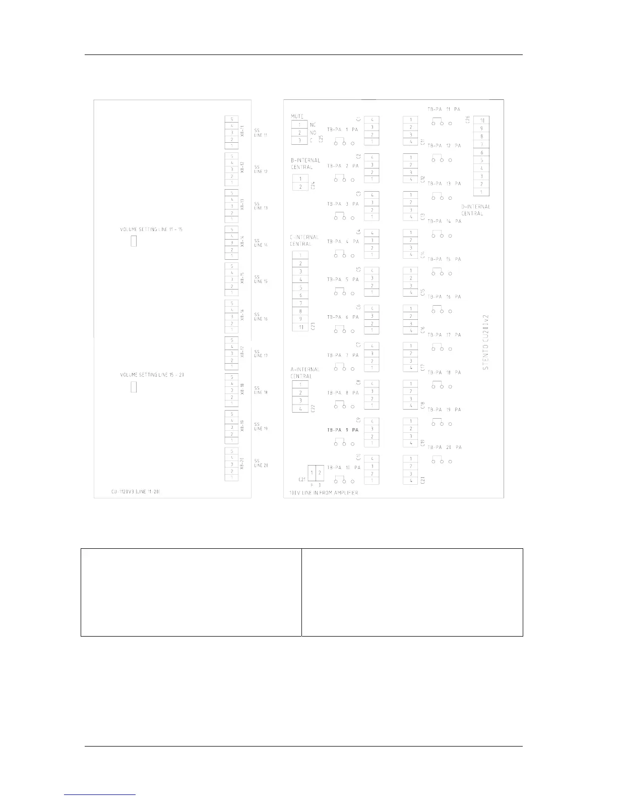
Fig. Additional PCB for CU-200 See drawing CU-200_lo for further details.
Terminal block X8 11-20 for Connection Substations.
Terminal no.3 – 4 24V DC to extra signal device.
Terminal no.5 is ground point for each substation
screen.
Terminal block C1-C20 for Connection Substations.
Terminal no.1 – 2 substation line low impedance
Terminal no.3 – 4 substation line 100V
Terminal block C25 MUTE for external alarm
system
Other terminal blocks for internal use.