Installation & User Manual System CTB-100V
12
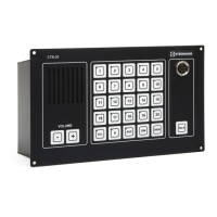
3.2.2 Operation panel CTB-10 & 20
The operation panels indoor can be flush or bulkhead mounted in a normal and ventilated indoor environment
with a temperature of 0 - 55
0
C. See drawing CTB-1020_dd1 for mounting details.
Note ! Make sure that it is sufficient space for cables and maintenance.
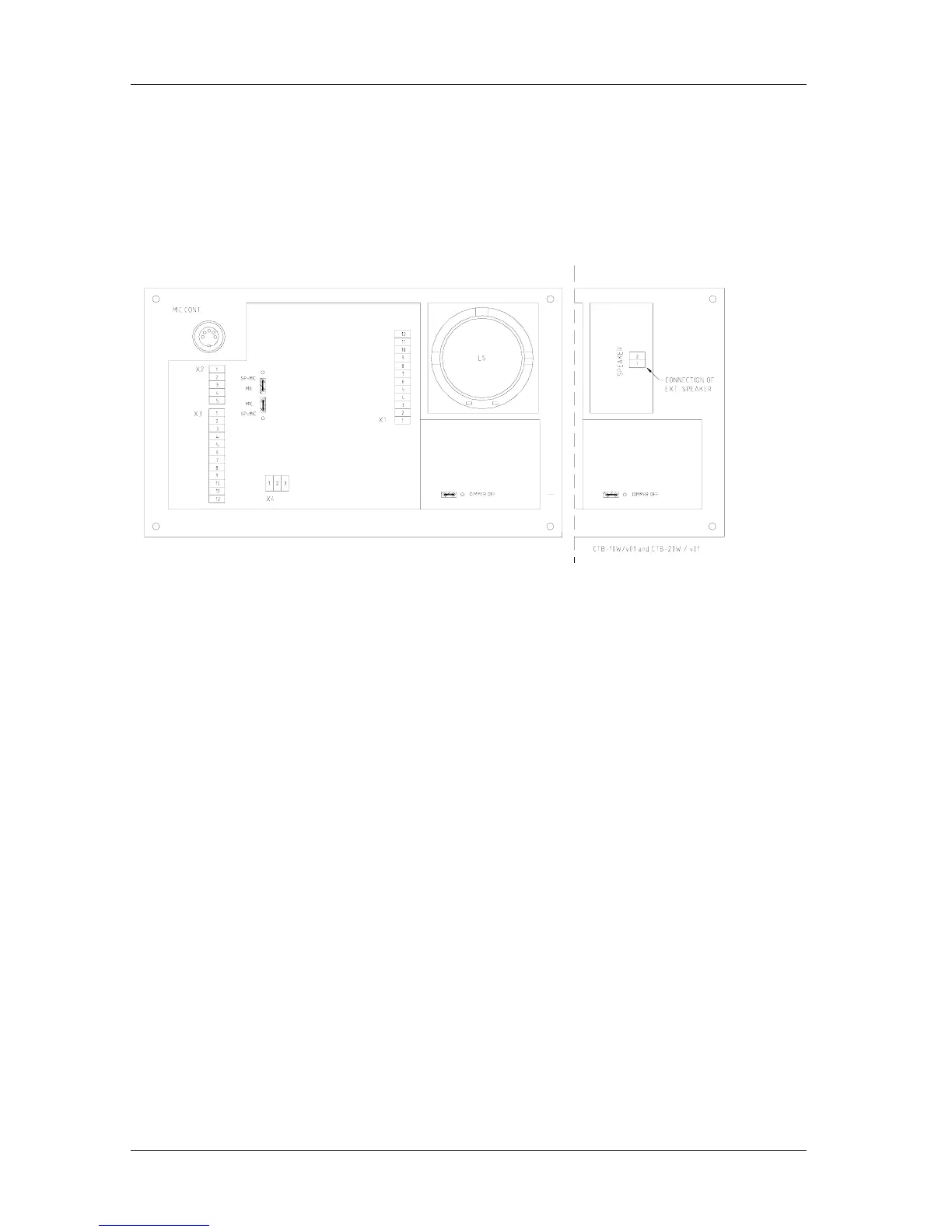
It is equipped with 2x cable gland PG-16 and plugable screw terminals for cables max.2,5mm
2
See drawing CTB-1020_lo for terminal and
Terminal block X1: For connection to the central unit.
Terminal block X2: Not in use
Terminal block X3 For connection to external loudspeaker, microphone and parallel microphone.
Terminal block X4 Potentional free contact for extra signal unit.
Terminal block SPEAKER 1-2 for external loudspeaker HP-8 (CTB-10W / V01, CTB-20W / V01)
3.2.3 CTB-10W / V01, CTB-20W / V01
This weather proof operation panels IP-66 is for bulkhead mounting only. Including
external loudspeaker HP-8 Ref. drawing CTB-1020W_dd for mounting details and datasheet for HP-8.
It is equipped with 2x cable gland PG-16 and plugable screw terminals for cables max.2,5mm
2
Ref. drawing CTB-1020_lo for lay out terminals drawing CTB-1020W_dd for mounting details and datasheet for
HP-8.
Note ! Make sure that it is sufficient space for cables and maintenance.
3.2.4 Identification sign plate CTB-panels
A sign plate with directory / substation number for all substations has to be placed close to the CTB-panels.
3.2.5 Substations and other equipment.
Ref. datasheets for dimension, cut out and mounting.
Note ! Make sure that it is sufficient space for cables and maintenance.
3.2.6 Identification sign plate substation
A sign plate with each substation number has to be placed on or close to each substation.
3.3 Cable requirements
All signal cables have to be approved ship-cable of type twisted pair with outer braided copper screen.
See cable connection drawings in chapter 6 for further details.
The screens must be interconnected in junction boxes and grounded in the central unit only.
Terminal block X8 1-20 terminal no.5 is ground point for each substation screen
Terminal block X1,2,3,4 / no.11 is ground point for each operation panel.
Power cable has to be approved ship cable min. 3 x 1,5mm
2
Note! The central unit has to be connected to the vessels central ground.
Proper grounding is essential for reliable operation.