Installation & User Manual System CTB-100V
30
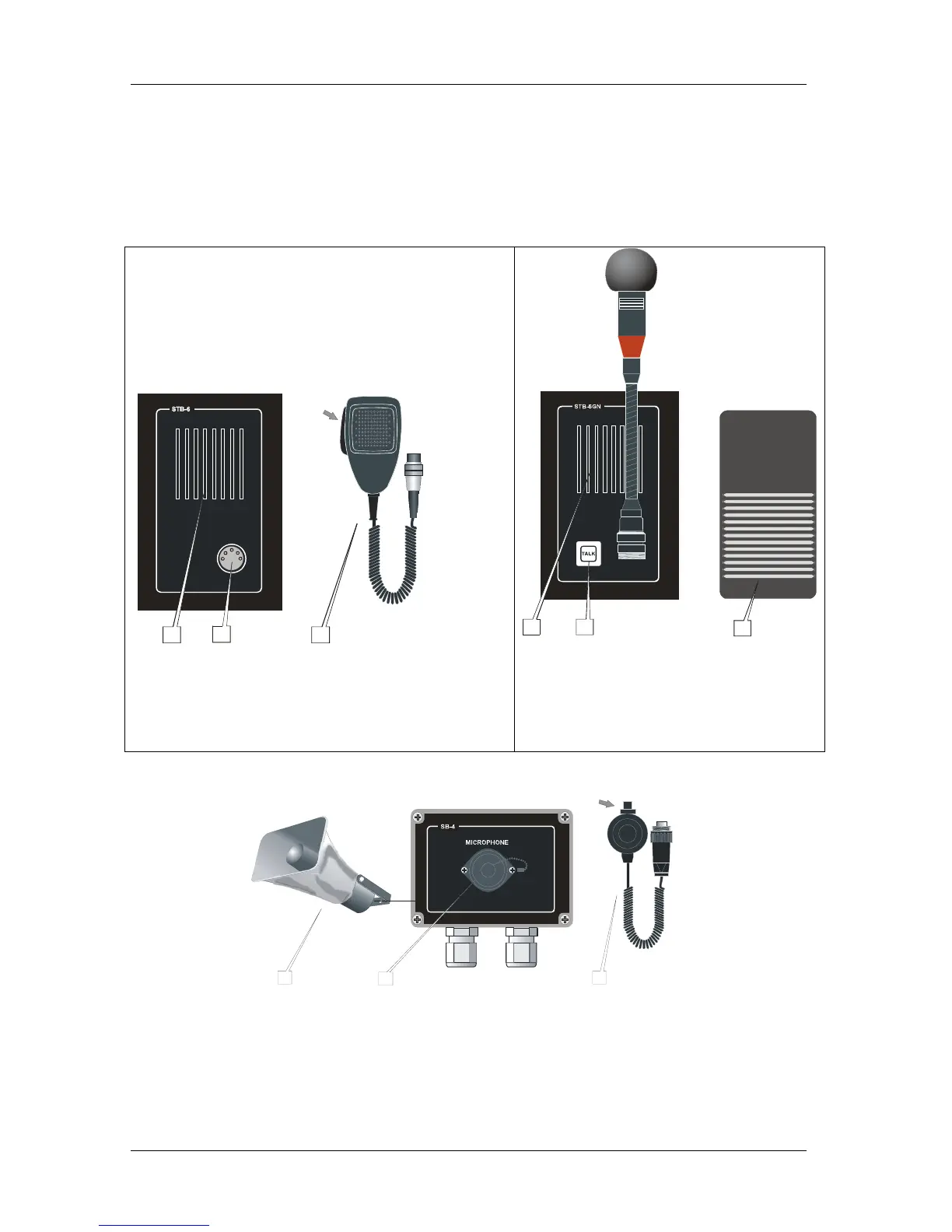
4.2 Parallel communication
Function with operation from parallel microphone / loudspeaker located on bridge wings,
or other locations near the operation panel, where parallel microphone / loudspeaker needed.
Two parallel stations can be connected. Communication is set up by the operationpanel.
Bridge wing unit will be in operation mode as soon as a station is selected on the operationpanel.
Figure 9 Parallel station STB-6 Figure 10 Parallel station STB-6GN
3
P
T
T
S
W
I
T
C
H
1
2
1. (Parallel to the central unit)
2. For microphone
3.
PTT switch = Push to talk button switch
Loudspeaker
Contact
Microphone ETC-1-TB with PTT switch
3
2
1
1. (Parallel to the central unit)
2. PTT switch for microphone
3.
PTT switch = Push to talk button switch
Loudspeaker
TALK
(Parallel to the central unit)
(Parallel to PTT switch )Footswitch
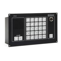
Figure 10 Parallel station SB-4
P
T
T
S
W
I
T
C
H
1
2
3
1. (Parallel to the central unit)
2. For microphone
3.
PTT switch = Push to talk button switch
Loudspeaker
Contact
Microphone Microphone P-66 with push to talk switch
(parallel to microphone on the central unit