Installation & User Manual System CTB-100V
34
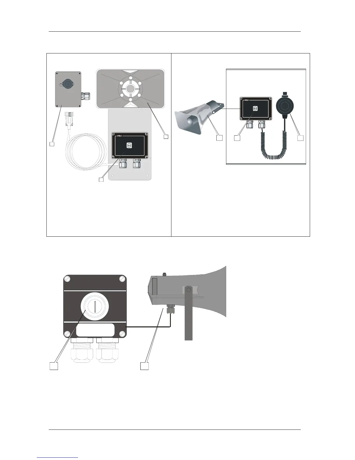
Figure 17 Substation VH-10M Figure 18 Substation VHM-10
10m cable
1
2
1.
CD-2 for VH-10M
2.
Push button switch for call to the central unit
3.
For communication from the central unit
Microphone for communication to the central unit.
Plugbox
CALL
Re-entrant Loudspeaker
3
PTT SWITCH
1
3
2
1. For communication from the central unitLoudspeaker
2. Push button switch for call to the central unit
3. P-66 fixed connected with PTT switch
PTT switch = Push to talk button switch
CALL
Microphone
CABINET
Figure 19 Substation NEBB-42EX / EX Loudspeaker
EEx de IIC T6 PTB Nr.Ex-87.B.1009
Ui 690V
CEAG
GHG 411
I
N
16A
1
2
1. Push to call switch
2. Re-entrant Loudspeaker EX.