Installation & User Manual System CTB-100V
10
3. INSTALLATION AND CONFIGURATION PROCEDURES
3.1 General
For proper installation and operation of the CTB-system we recommend to read this section
thoroughly together with installation drawings in chapter 6.
Make sure that all mounting and cabling are correct before switching on the system
3.2 Mounting & Terminal configuration.
3.2.1 Central unit CU-100 & CU-200
The central unit is the basis of a system. It should be bulkhead mounted in a normal and ventilated indoor
environment with a temperature of max. 55
0
C. See drawing CU_dd for mounting details.
Note ! Make sure that it is sufficient space for cables and maintenance.
It is equipped with pluggable screw terminals for cables max.2,5mm
2
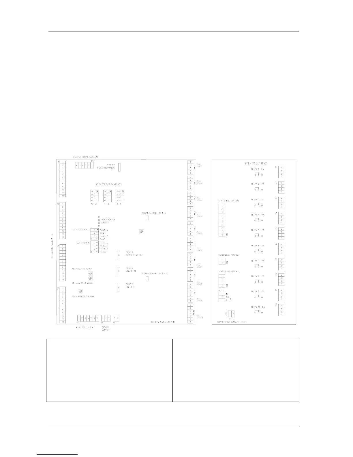
Fig. CU-100 See drawing CU-100_lo for further details.
Terminal block X1-X4 Connection of operation
panels.
Terminal block X5 Output to the PA-system.
Terminal block X6 AUX and PA input.
Terminal block X7 Power supply.
Terminal block X8 1-10 for Connection Substations.
Terminal no.3 – 4 24V DC to extra signal device.
Terminal no.5 is ground point for each substation
screen.
Terminal block C1-C10 for Connection Substations.
Terminal no.1 – 2 substation line low impedance
Terminal no.3 – 4 substation line 100V
Terminal block C25 MUTE for external alarm
system
Other terminal blocks for internal use.