15
Installation
Pressurizing from an external pressure source
WARNING! This pedestal must be pressurized only with clean, dry air or nitrogen. A pressure reducing valve must be tted to the
pressure line between the gas cylinder and the outlet connection of the hose. The reducing valve must be screwed into the gas cylinder
outlet. The maximum pressure on the outlet side of the reducing valve must not exceed 11.7 bar (170 psi).
Do not pressurize the pedestal beyond the maximum safe working pressure indicated by the leading edge of the red sector on the
gauge. The pedestal is tted with a pressure relief valve as a safeguard against over-pressurization.
Do not attempt to adjust the pressure relief valve.
WARNING! A pressurized pedestal will rise rapidly when safety catch is released. Do not release safety catch when pedestal is
pressurized and balancing load is not installed. Always restrain the pedestal by hand pressure on the steering ring when the safety catch
is released.
To pressurize the pedestal from an external pressure source, proceed as follows:
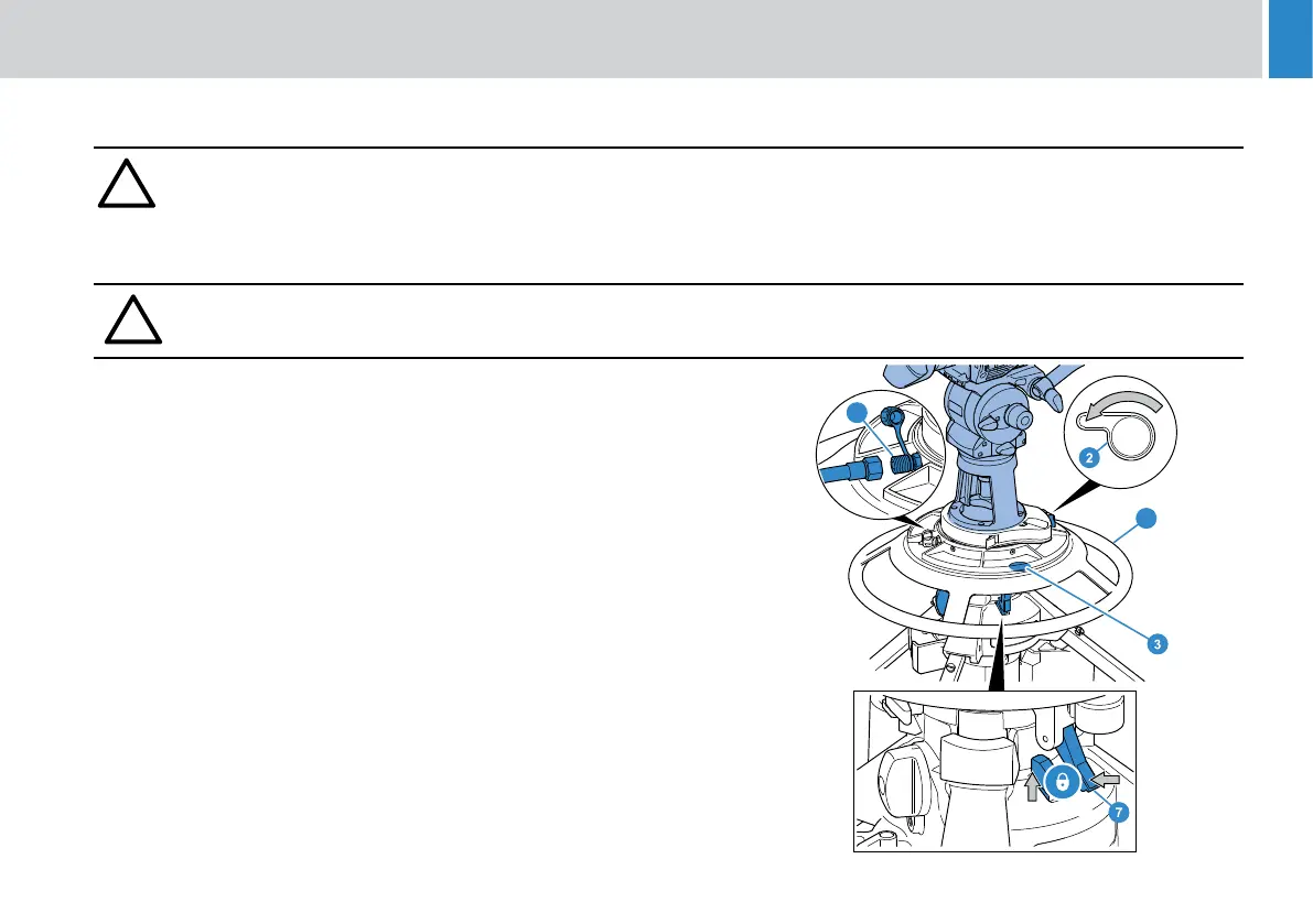
1. Set the control valve (2) to the WORK position.
2. Push down on the steering ring (20) against any residual pressure and engage the
safety catch (7).
3. Attach the intended payload, Fitting and balancing the load on page 15
4. Turn the Steering ring (4) so the pressure gauge (3) can be seen through the
weight tray
5. Remove the Schrader valve cap (22) and connect the charging line from the
pressure source.
6. Turn on the pressure supply and slowly increase the pedestal pressure. Shut o
the supply when maximum working pressure is reached, indicated by the lower
edge of the red sector on the gauge (3).
7. Disconnect the hose from the pedestal charging valve, but do not ret the
Schrader valve cap at this stage.
22
20
Note! In the event that the pedestal air pressure has
dropped to 0 psi, proceed as follows:
Follow steps 3 to 4. The pump features a shock
function (Lever in Position A), this allows the pump to
store pressure with every stroke up to approximately
75psi. When this pressure is achieved turn the lever to
position B. This will force the O-ring in the pedestal to
seal. Resume from step 5.