17
Installation
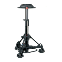
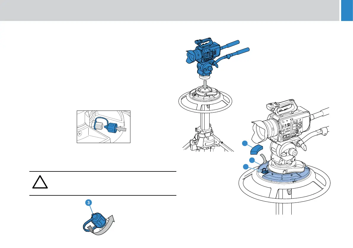
1. Fit the adaptor to the ped rst, then the head followed by the
camera, blue indicates moving parts not assembly sequence. Once
the head is tted follow head and accessories manuals to securely
t all of he payload (which may include camera, lens, teleprompter,
viewnder and accessories. .
2. With the full payload tted, hold the steering ring down and release
the safety catch carefully allowing the top stage of the pedestal
to extend. Ensure pan bars, prompters, lenses etc are tted.
Attaching these items at a later stage may upset the pedestal
balance.
3. Using the Schrader valve cap, carefully reduce the pressure
in steps of 0.15- 0.20bar (2-3psi) until the payload is correctly
balanced. Ret the Schrader valve cap (3)
A correctly pressurized pedestal will balance its payload, it may be
moved to any position over the full on-shot stroke with minimum eort
and will maintain its position when the steering ring is released.
!
WARNING! The Schrader valve cap (3) forms a primary
pressure seal. Always replace the cap and screw it down
nger-tight.
3. Fine balance and temperature correction may be achieved by
adding or removing trim weights (8).
8
21
22
8