15
Contents
Previous
Page
First
Page
Next
Page
Previous
View
Fitting a camera
9 To fit a camera, proceed as follows:
9.1 Lower the mounting to a convenient working height.
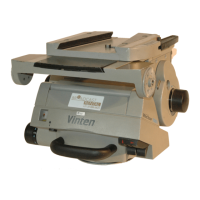
9.2 If not already fitted, install the wedge adaptor (15) in the middle position on the sliding plate (8)
(See “Repositioning the wedge adaptor” on page 25).
9.3 Attach the wedge to the camera/lens.
9.4 Ensure that the centre lock is engaged (See “Locking the platform” on page 16).
9.5 Slide the wedge adaptor operating lever (1) forward (parallel to the wedge) about 6mm
(1/4 in.) against spring tension. Pull the operating lever out, away from the body of the wedge adaptor,
as far as it will go.
9.6 Insert the camera wedge into the wedge adaptor and push it forward into full engagement. Push
in the operating lever until it lies parallel with the wedge adaptor body. During this operation resistance
of the spring-loaded over-centre mechanism will be felt. As the lever reaches the end of its travel it will
slide back (parallel to the wedge) to the locked position.
9.7 Confirm that the lever is in the locked position. This is indicated by coloured bands above the
lever. When the green band only is visible, the lever is locked. If any of the red band can be seen, the
lever is not locked.
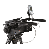
9.8 Install the remainder of the payload (lens, zoom and focus controls, viewfinder, prompter etc).
Balancing the head
10 Balancing the head consists of positioning the payload fore and aft on the head so that its C of G is
immediately above the platform pivot, then compensating for the payload C of G height using the balance
adjustment knob.
11 Position the payload fore and aft as follows:
11.1 Ensure that the centre lock is engaged (See “Locking the platform” on page 16) and that the
camera and all accessories are fitted.
WARNING!: Do not rely on the tilt brake when changing the payload. always engage the
centre lock.
Ensure that the weight and C of G height of the total payload is within the range for
which the head is designed - up to 70 kg (154 lb) with C of G height from 80 mm (3 in.) to
200mm (8 in.) for Vector 70 or 80 mm (3 in.) to 250 mm (10 in.) for Vector 70H.
NOTE: It is important that the pan bar(s) and all camera accessories (lens, zoom and focus
controls, viewfinder, prompter etc.) are fitted in their operational position before balancing
the head. Any equipment fitted or adjusted later will unbalance the head.