48
Contents
Previous
Page
First
Page
Next
Page
Previous
View
31.13 Loosely install screw (22) in slide clamp lever (23) Position lever in platform and screw in slide
clamp screw (25) until it engages with lever. Position slide clamp (18) in platform and fully screw in slide
clamp screw (25).
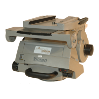
32 To install the platform assembly, proceed as follows (Fig 6.6):
32.1 If removed, install a Spirol pin (4) in each platform pivot block (5).
32.2 Position the platform (2) over the pivot blocks and fully engage. Ensure pins (4) do not protrude
above the surface. Secure the platform to the pivot blocks with six screws (1).
32.3 Referring to Fig 6.10, slide the slide plate (1) into the platform and engage with the worm gear.
Using the platform adjustment knob (13), position the platform so that the two stop screws (7) can be
installed.
32.4 Adjust the slide clamp as follows:
32.4.1 Pull the slide clamp lever (23) fully upwards.
32.4.2 Screw in the slide clamp screw (25) to apply the clamp.
32.4.3 Tighten screw (22).
32.4.4 Move the lever (23) over its full range and ensure that, in the clamped position it
prevents the platform slide from being moved, while in the released position it allows free
adjustment of the slide. Re-adjust if necessary.
32.5 Affix the self-adhesive slide clamp cover (24) to the platform.
Tilt drag mechanism
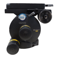
33 To assemble the tilt drag mechanism, proceed as follows (Fig 6.9):
33.1 If removed, install two dowel pins (9), two dowel pins (10) and dowel pin (11) in tilt drag cover
(25).
33.2 Install ‘O’ ring (23) in outer boss (22).
33.3 Install outer boss (22) on the tilt drag cover (24) and secure with three screws (12).
33.4 Lubricate the two thrust washers and the thrust race (13) with LM grease and Install in the outer
boss (22).
33.5 Install ‘O’ ring (14) on the knob boss/threaded shaft (19) and install knob boss/threaded shaft in
the outer boss (22). Install drag knob retainer (21) and secure with three screws (20).
NOTE: The slide plate is installed after the platform is attached to the head.
NOTE: Ensure the mechanism housing is level prior to installation of the platform.
NOTE: The drag shoe assemblies (5, 28) and actuator links (6, 26) are handed.