With a bus coupler bus interface and power module are integrated to
one casing. With the bus interface you get access to a subordinated
bus system. As head module via the integrated power module for
power supply the bus interface is supplied as well as the electronic of
the connected periphery modules. The DC 24 power section supply
for the linked periphery modules is established via a further connec-
tion at the power module. By installing of up to 64 periphery modules
at the bus coupler, these are electrically connected, this means these
are assigned to the backplane bus, the electronic modules are power
supplied and each periphery module is connected to the DC 24V
power section supply.
CAUTION!
Bus interface and power module of the bus coupler may
not be separated! Here you may only exchange the elec-
tronic module!
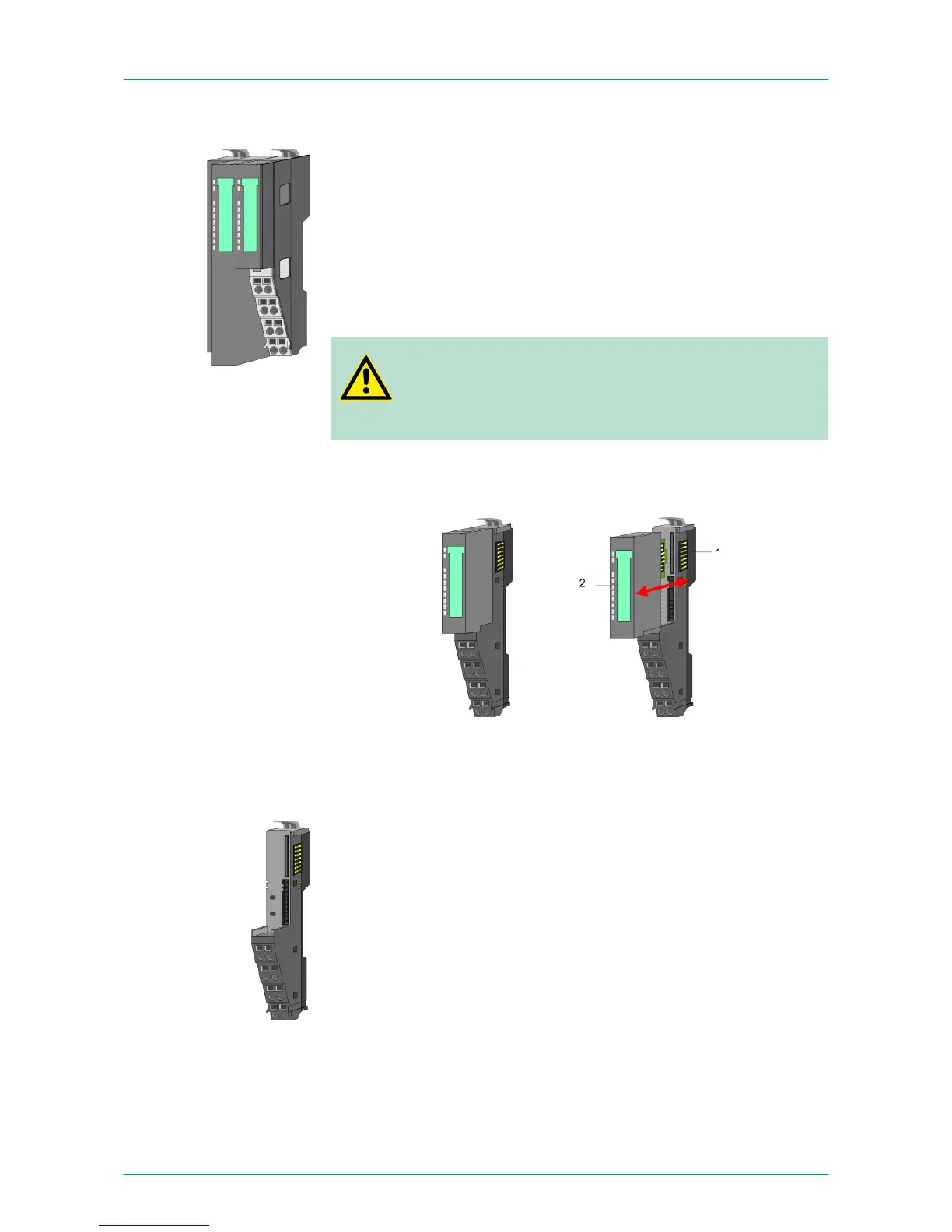
Each periphery module consists of a terminal and an electronic
module.
1 Terminal module
2 Electronic module
The terminal module serves to carry the electronic module, contains
the backplane bus with power supply for the electronic, the DC 24V
power section supply and the staircase-shaped terminal for wiring.
Additionally the terminal module has a locking system for fixing at a
mounting rail. By means of this locking system your SLIO system may
be assembled outside of your switchgear cabinet to be later mounted
there as whole system.
Bus coupler
Periphery modules
Terminal module
VIPA System SLIOBasics and Assembly
System conception
HB300 | FM | 050-1BA00 | GB | 14-36 10