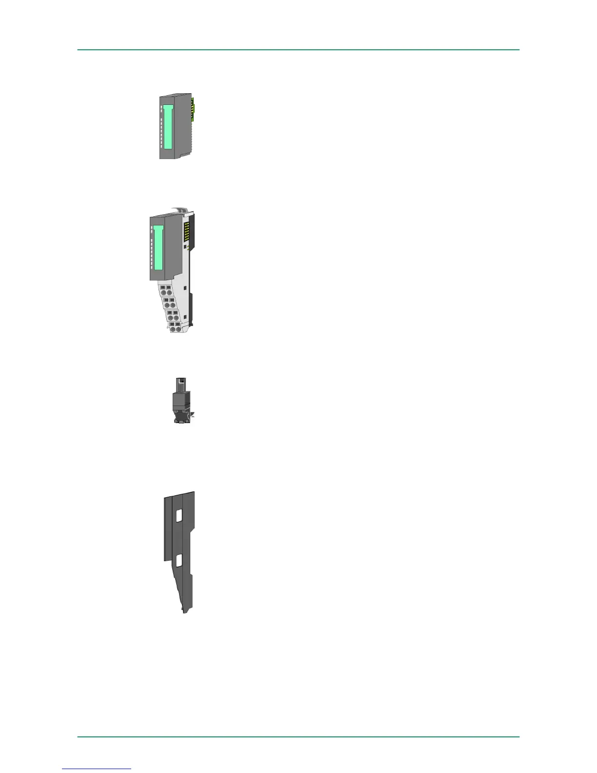
The functionality of a SLIO periphery module is defined by the elec-
tronic module, which is mounted to the terminal module by a safe
sliding mechanism. With an error the defective module may be
exchanged for a functional module with standing installation.
At the front side there are LEDs for status indication. For simple
wiring each module shows a corresponding connection diagram at
the front and at the side.
In the System SLIO the power supply is established by power mod-
ules. These are either integrated to the bus coupler or may be
installed between the periphery modules. Depending on the power
module isolated areas of the DC 24V power section supply may be
defined respectively the electronic power supply may be extended
with 2A. For better recognition the colour of the power modules are
contrasting to the periphery modules.
The shield bus carrier (order no. 000-0AB00) serves to carry the
shield bus (10mm x 3mm) to connect cable shields. Shield bus car-
riers, shield bus and shield fixings are not in the scope of delivery.
They are only available as accessories.
The shield bus carrier is mounted underneath the terminal of the ter-
minal module. With a flat mounting rail for adaption to a flat mounting
rail you may remove the spacer of the shield bus carrier.
With each bus coupler, to protect the backplane bus connectors,
there is a mounted bus cover in the scope of delivery. You have to
remove the bus cover of the bus coupler before mounting a SLIO
module. For the protection of the backplane bus connector you
always have to mount the bus cover at the last module of your system
again.
The bus cover has the order no. 000-0AA00.
Electronic module
Power module
Accessories
Shield bus carrier
Bus cover
VIPA System SLIO Basics and Assembly
System conception
HB300 | FM | 050-1BA00 | GB | 14-36 11