© 2005 Directed Electronics—all rights reserved
1199
This input comes from the factory set to 2 activation pulses. This means that it is necessary to have 2 consecu-
tive ground pulses on the white/blue wire for the remote start to activate or to deactivate. The same holds true
for the remote control activation when set to a two pulse setting it is necessary to press the button twice
for the remote start to activate or deactivate.
NNOOTTEE::
When the activation pulse count has been programmed to 1 or 2 pulses it will affect both
activation inputs; the White/Blue wire and the remote control activation.
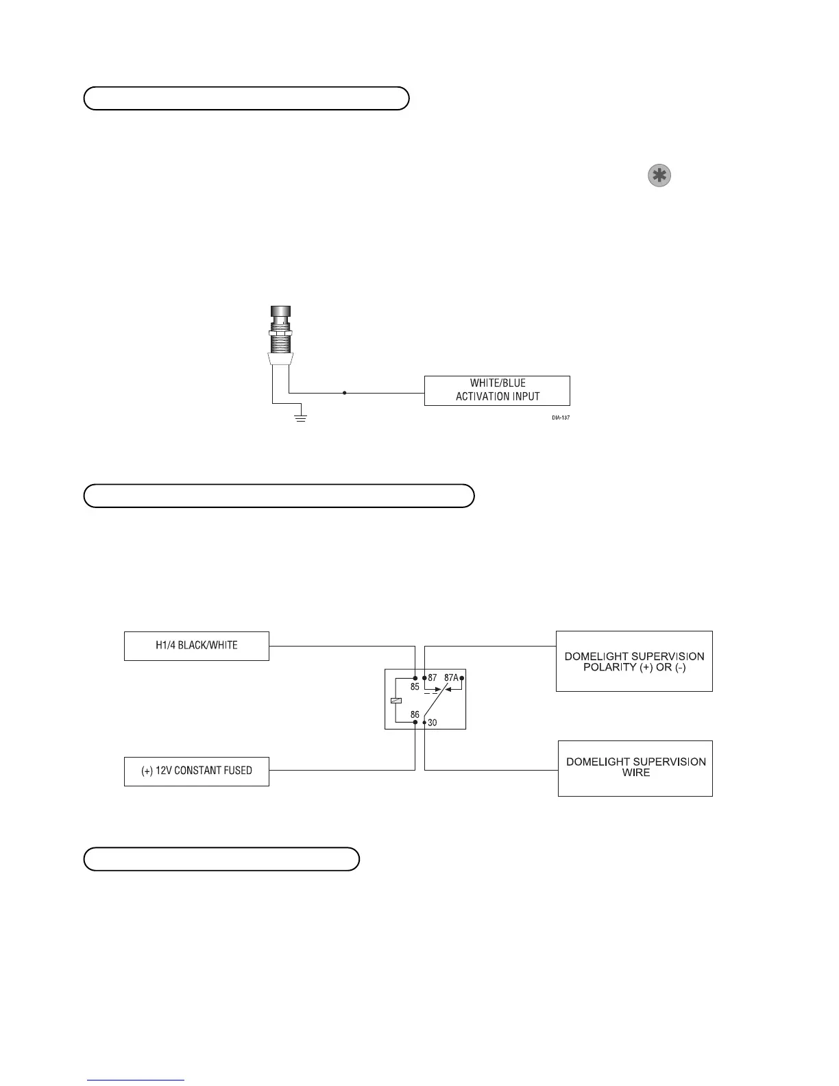
Connect this wire to the optional domelight supervision relay as shown below:
IIMMPPOORRTTAANNTT!!
This output is only intended to drive a relay. It cannot be connected directly to the
domelight circuit, as the output cannot support the current draw of one or more light bulbs.
Most vehicles use negative door trigger circuits. Connect the green wire to a wire which shows ground when any
door is opened. In vehicles with factory delays on the domelight circuit, there is usually a wire that is unaffected
by the delay circuitry. This wire will report Zone 3.
HH11//55 GGRREEEENN ((--)) ddoooorr ttrriiggggeerr iinnppuutt,, zzoonnee 33
HH11//44 BBLLAACCKK//WWHHIITTEE ((--)) 220000 mmAA ddoommeelliigghhtt ssuuppeerrvviissiioonn oouuttppuutt
HH11//33 WWHHIITTEE//BBLLUUEE rreemmoottee ssttaarrtt ((--)) aaccttiivvaattiioonn iinnppuutt
 Loading...