Do you have a question about the Viper 700 ESP and is the answer not in the manual?
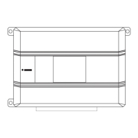
Details the pinout for the 16-pin H1 connector, outlining each pin's function.
Details the pinout for the 10-pin H2 connector, outlining each pin's function.
Details the pinout for the 6-pin H3 door lock connector, outlining each pin's function.
Details the connection for the H1/1 wire, intended for domelight supervision output.
Explains connecting the H1/2 wire for sensor input, triggering Warn Away or full alarm.
Guides connection of H1/3 wire for positive (+) door trigger input, critical for all doors.
Describes H1/4 connection for negative input, ideal for hood/trunk pins or sensors.
Details H1/5 connection for negative (-) door trigger input; must sense all doors.
Explains connecting H1/6 to siren data output for disarming via siren key.
Details H1/7, providing ground when armed, ceasing upon disarming.
Guides connection for parking light outputs, dual isolated relays for flashing lights.
Explains H1/9 for honking the vehicle horn, programmable for lock/unlock pulses.
Describes H1/10 & H1/12 for fuel or ignition kill, requiring cutting wires.
Details connecting H1/11 to the siren input for audible alarm output.
Explains H1/13 & H1/14 for fuel/ignition kill, similar to H1/10 & H1/12.
Details H1/16 input for dual parking light outputs, determining polarity.
Guides connection of H2/1 to ignition wire for triggering alarm upon ignition.
Indicates that the H2/2 wire has no functional purpose in the system.
Explains proper grounding procedure for H2/3 to bare metal for all components.
Details connection of H2/4 to the Valet switch for programming and Valet Mode.
Describes H2/5 output for Channel 4 functions, programmable as validity or latched.
Guides connection of H2/6 to a constant 12V source with a 15-amp fuse.
Explains H2/7 & H2/10 for starter wire interruption.
Details H2/8 output for Channel 2, used for trunk release or relay functions.
Describes H2/9 output for Channel 3, programmable for various output types.
Describes Type A door lock systems, common in GM, Ford, Chrysler, newer Saturns, VW, BMW.
Describes Type B door lock systems, common in Asian vehicles, early Saturn, BMW, Porsche.
Describes Type C door lock systems with directly wired reversing-polarity switches.
Describes Type D systems requiring added actuators for doors without power locks.
Describes Type E systems using electrically activated vacuum for door locks.
Describes Type F systems for Nissan Sentra, 240SX, 300ZX, and Mazda MPVs.
Describes Type G systems commonly found in Ford, Mazda, Chrysler, GM vehicles.
Describes Type H systems commonly found in Ford, Mazda, Chrysler, GM vehicles.
Wiring diagram for Type A positive-triggered, relay-driven door lock systems.
Wiring diagram for Type B negative-triggered, relay-driven door lock systems.
Wiring instructions for Type C reversing polarity door lock systems.
Wiring for Type D systems requiring after-market actuators for door locks.
Wiring for Type E electrically-activated vacuum door lock systems.
Wiring for Type F one-wire systems, cut to lock, ground to unlock.
Wiring for Type G positive multiplex door lock systems, often with resistors.
Wiring for Type H negative multiplex door lock systems, often with resistors.
Details the super-bright LED connection and mounting for status indication.
Explains the 3-pin port for PC programming using Bitwriter or interface module.
Describes the internal shock sensor and its adjustment for sensitivity.
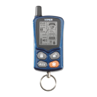
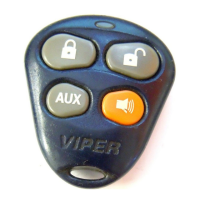
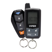
Details the standard transmitter configuration for arm/disarm/panic with separate buttons.
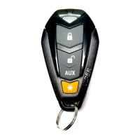
Describes single-button configuration for arm/disarm/panic functions.
Lists and describes basic system features and their default settings.
Lists and describes advanced system features and their settings.
Provides detailed explanations for basic system features.
Provides detailed explanations for advanced system features.
| Panic Mode | Yes |
|---|---|
| Keyless Entry | Yes |
| LED Status Indicator | Yes |
| Number of Remotes Included | 2 |
| Dual Zone Shock Sensor | Yes |
| Starter Disable | Yes |
| Type | Car Security System |
| Security Features | Starter Disable, Anti-Carjacking |
| Remote Control | Yes |