© 2000 Directed Electronics, Inc. Vista, CA 5
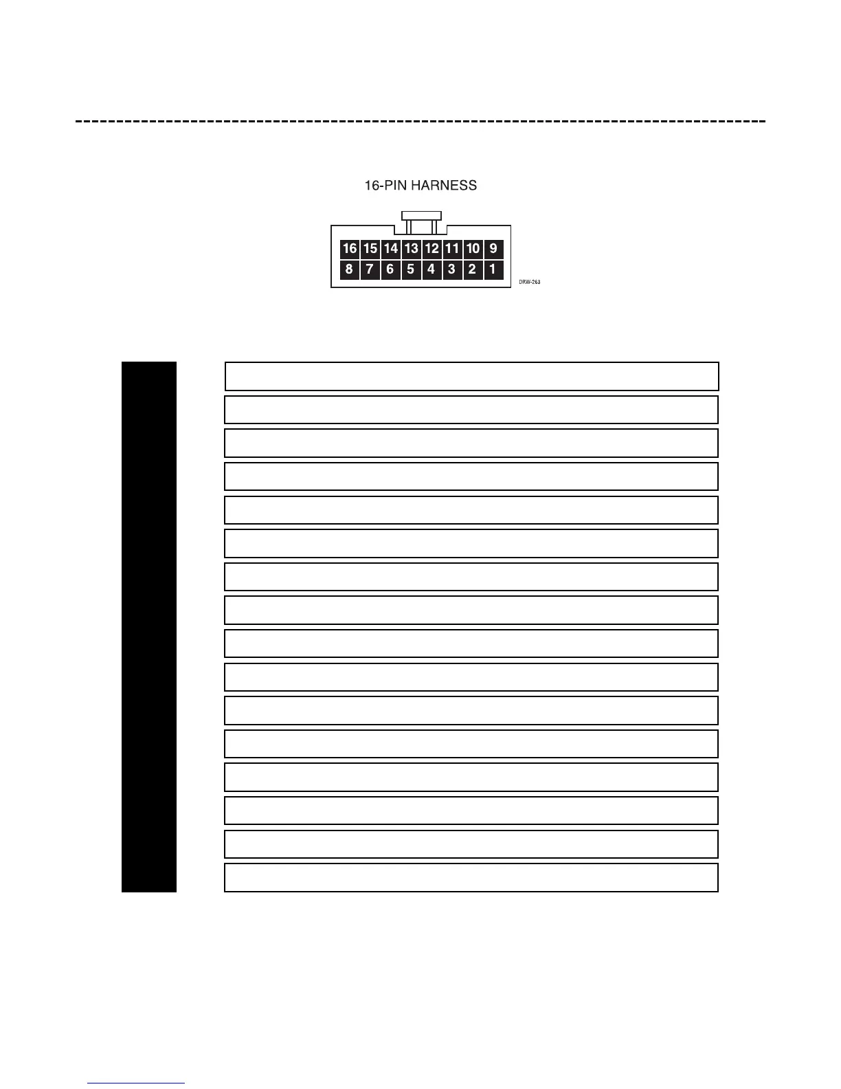
primary harness (H1), 16-pin connector
NOTE: The labels for the pin numbers of this harness are located on the front of the plug, which is
the same side of the plug depicted in this diagram.
______
______
______
______
______
______
______
______
______
______
______
______
______
______
______
______
*IMPORTANT! The siren data wire should only be connected to the siren’s VIOLET tag wire. Do not
connect this wire to anything else.
LIGHT IN (PARKING LIGHT INPUT)
LIGHT OUT 5 AMP (PARKING LIGHT OUTPUT #2)
NORMALLY OPEN INTERRUPT OUTPUT #3
NORMALLY OPEN INTERRUPT INPUT #3
NORMALLY OPEN INTERRUPT OUTPUT #2
(-) SIREN 200 mA (NEGATIVE SIREN OUTPUT)
NORMALLY OPEN INTERRUPT INPUT #2
(-) HORN 200 mA (NEGATIVE HORN HONK OUTPUT)
LIGHT OUT 5 AMP (PARKING LIGHT OUTPUT #1)
(-) STARTER 500 mA (NEGATIVE GROUND-WHEN-ARMED OUTPUT)
SIREN DATA* SIREN DATA INPUT
(-) DOOR (NEGATIVE DOOR TRIGGER INPUT, ZONE 3)
(-) INST (NEGATIVE INSTANT TRIGGER, ZONE 1)
(+) DOOR (POSITIVE DOOR TRIGGER INPUT, ZONE 3)
(-) SENSOR (NEGATIVE SENSOR, ZONE 4 MULTIPLEX)
(-) DOME 200 mA ( NEGATIVE DOMELIGHT SUPERVISION OUTPUT)
H1/1
H1/2
H1/3
H1/4
H1/5
H1/6
H1/7
H1/8
H1/9
H1/10
H1/11
H1/12
H1/13
H1/14
H1/15
H1/16