Do you have a question about the Viper 771XV and is the answer not in the manual?
Lists all components included with the Viper Model 771XV.
Provides critical safety precautions for installation and operation of the remote start system.
Key considerations and recommendations before starting the installation process.
Steps and checks to perform after the installation is complete.
Guidelines for selecting an optimal and secure location for the siren.
Recommendations for placing the control module securely and away from heat sources.
Best practices for mounting the antenna for optimal range and visibility.
Advice on where to mount the Stinger Doubleguard shock sensor for best performance.
Important considerations for the placement of the valet/program switch.
Recommendations for mounting the status LED for visibility.
Guidance on locating the optional starter kill relay discreetly.
Tips for mounting the relay satellite near the ignition switch harness.
Crucial advice on using a digital multimeter for wire identification.
Methods for finding and connecting to a constant 12V power source.
Procedure to locate the vehicle's 12V switched ignition wire using a multimeter.
Steps to identify the vehicle's starter wire using a multimeter.
Method to locate the accessory wire that powers climate control.
Procedure to find the tachometer signal wire using AC voltage measurement.
Locating the diesel wait-to-start bulb wire for proper system integration.
Techniques for identifying the positive parking light wire.
Details of the 12-pin primary harness wiring and functions.
Details of the 6-pin secondary harness wiring and functions.
Wiring details for the 3-pin door lock harness.
Wiring details for the 7-pin remote start primary harness.
Wiring for the heavy gauge wires of the relay satellite connector.
Wiring details for the 5-pin H3 remote start secondary harness.
Wiring details for the 2-pin H4 horn harness.
Explains the function and connection of the H1/1 ground-when-armed output wire.
Details on connecting the H1/2 light flash output for positive or negative triggers.
Describes the H1/3 remote start activation input and pulse count settings.
Explains the H1/4 domelight supervision output and its connection to a relay.
Details the H1/5 door trigger input, typically for negative trigger systems.
Describes the H1/6 trunk trigger input for zone 1.
Details the H1/7 door trigger input for positive trigger systems.
Instructions for making a proper chassis ground connection with wire H1/8.
Explains the connection for the H1/10 siren output wire.
Details the H1/11 connection for constant 12V power input.
Describes the H1/12 output for trunk release or other relay functions.
Details the H2/1 factory alarm disarm output and its use with a relay.
Explains the H2/2 connection for the wait-to-start input, including polarity changes.
Describes the H2/3 signal for factory alarm rearming.
Details the H2/4 channel 4 output and its programmable modes.
Explains the H2/5 second unlock output functionality.
Guide for connecting the relay satellite to the vehicle's ignition switch.
Connecting the 12V constant inputs for high current outputs.
Connecting accessory and ignition output wires.
Details on the ribbon and auxiliary relay output harnesses.
Describes the H3/1 status or rear defogger output.
Explains the H3/2 hood pinswitch input for safety shutdown.
Details the H3/3 brake switch input for safety shutdown.
Describes the H3/4 tachometer input for engine speed monitoring.
Explains the H3/5 neutral safety switch input for preventing in-gear starts.
Wiring details for the H4 horn output.
Discusses vehicles without electrical neutral safety switches and potential issues.
Information on bypassing GM Passlock I and II systems.
Details on bypassing Passkey III and other transponder systems.
Guide to connecting the LED and valet/program switch to the module.
Information on using the 3-pin port for unit programming.
Wiring for the GREEN input for dual-stage sensors.
Wiring for the BLUE input for dual-stage sensors.
Connection details for RED (+)12V constant and BLACK (-) ground wires.
Step-by-step guide to teaching the system the tach signal.
Explanation of the tach threshold and light flash jumpers.
Adjusting tach threshold for vehicles with low ignition voltage.
Setting the light flash output to positive or negative polarity.
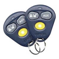
Procedure for teaching transmitters to the system.
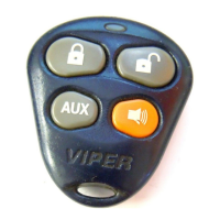
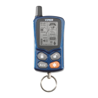
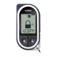
Details on the standard transmitter button assignments.
Step-by-step guide to accessing the system features programming menu.
Instructions for navigating and programming multiple features within a menu.
Lists and describes basic system features and their settings.
Lists and describes advanced system features and their settings.
Lists and describes remote start specific features and settings.
Detailed explanation of basic system features (1-1 to 1-7).
Detailed explanation of basic system features (1-8 to 1-14).
Introduction to the advanced features menu.
Detailed explanation of advanced features (2-3, 2-7, 2-8).
Detailed explanation of advanced features (2-11, 2-12, 2-13).
Lists and describes remote start options (3-1 to 3-3).
Explains how the Nuisance Prevention Circuitry bypasses zones.
Configuration for diesel timer wait-to-start input.
Settings for timer mode and run time.
Instructions for entering and exiting Valet Mode via switch or transmitter.
How to enter and exit Timer Mode for scheduled engine starts.
Identifies trigger types and their corresponding zone numbers.
Procedure to access and interpret shutdown diagnostic codes.
Common issues and solutions related to alarm triggers and sensors.
Common problems and fixes for remote start activation issues.