24 DE5467IP
Go over the table in Appendix B column by column. If, for
instance, the “BY ARM AWAY” column has “X”s marked in
the rows pertaining to units 1, 5 and 15 - then arm AWAY
the system and verify that the appliances controlled by
these units are actually activated upon arming.
Continue in the same manner in the following columns,
always creating the state or event that will activate the
relevant units. Verify that all appliances are activated as
programmed.
IMPORTANT! Before testing “BY TIMER” and “BY ZONE”,
make sure that these forms of control are permitted - click
repeatedly and verify that the display shows:
BY TIMER ON
and:
BY SENSOR ON
A dark box at the extreme right means that these functions
are enabled.
The easiest way for test timed activation is to select the
ninth item in the installer’s menu (”10. USER SETTINGS”)
and set the system clock a few minutes before the relevant
“start time”. Do not forget to return the clock to the correct
time after completion of this test.
5.5 Emergency Transmitter Test
Initiate transmission from each transmitter enrolled to an
emergency zone (according to the list in Table A3,
Appendix A). For example, upon pressing the transmit
button of an emergency transmitter enrolled to zone 22,
the display should read:
Z22 EMERGENCY
(alternating)
VIOLATED
It is advisable to let the central station know that you are
conducting this test, or just disconnect the telephone line
from the PowerMax+ during the test, to prevent false
alarms.
6. MAINTENANCE
6.1 Dismounting the Control Panel
A. Release the PowerMax+ unit from its bracket, as shown
in figure 3.2, step 1-3.
B. Separate the PowerMax+ unit from its bracket.
6.2 Replacing the Backup Battery
Replacement and first-time insertion of battery pack is
similar (see figure 3.1).
With fresh battery pack, correct insertion and tightened
battery compartment lid, the TROUBLE indicator should
extinguish. However, the “MEMORY” message will now
blink in the display (caused by the “tamper” alarm you
triggered when opening the battery compartment lid). Clear
it by arming the system and immediately disarming.
6.3 Fuse Replacement
The PowerMax+ has two internal fuses that have
automatic reset. Therefore, there is no need to replace
fuses.
When overcurrent condition occurs, the fuse cuts off the
circuit current. Upon fault current being removed, the fuse
is automatically reset and allows current flow through the
circuit again.
6.4 Replacing/Relocating Detectors
Whenever maintenance work involves replacement or re-
location of detectors, always perform a full diagnostic test
according to par. 4.9.
Remember! A "poor" signal is not acceptable, as stated at
the end of the test procedure.
7. READING THE EVENT LOG
Up to 100 or 250 events (according to the purchased
version) can be stored the event log. You can access this
log and review the events, one by one. If the event log fills
up completely (100 events), the oldest event is deleted
upon registration of each new event.
The
date and time of occurrence are memorized for each
event.
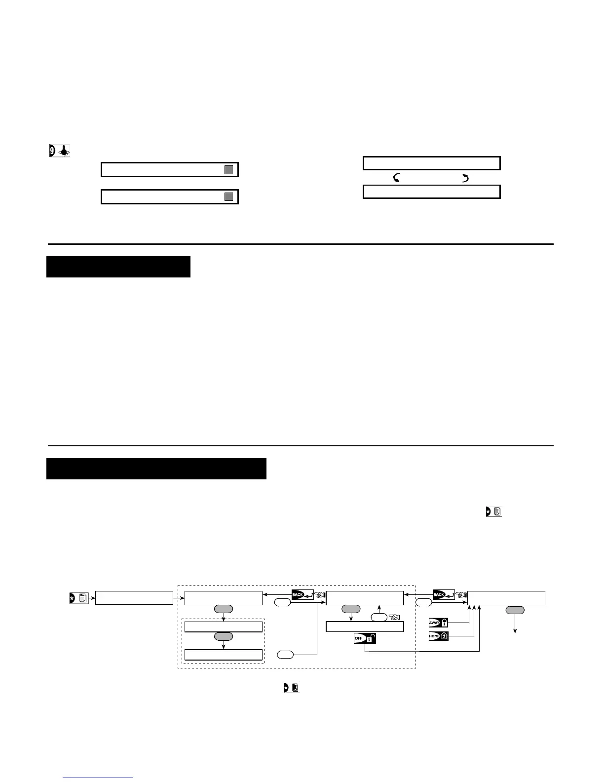
When reading the event log, events are shown in
chronological order - from the newest to the oldest. Access
to the event log is provided by clicking the
key and not
through the installer’s menu. Reading and erasing process
of the event log is shown in the next drawing.
OK
OK
Oldest Event
Latest Event
LIST OF EVENTS
OK
CODE _ _ _ _
(Enter 4-digit
installer code)
(*)
(**)
<OK TO EXIT
CLEAR EVENT LOG
NEXT
NEXT
<OFF> TO DELETE
NEXT
NEXT
(Return to normal
operation)
OK
(***)
Figure 7 - Reading / Erasing the Event Log
* While the system is in normal operation mode, click
to review the event log.
** Event is displayed in 2 parts, for example, "Z13 alarm" then "09/02/00 3:37 P". The two displays will be shown
alternately until clicking OK again to move to the next event or until the end of the event log (4 minutes).
*** Applicable only if installer code is entered.