DE5467IP 15
4.5 DEFINING COMMUNICATION PARAMETERS
Preliminary Guidance
This mode allows you to adapt the telephone
communication parameters to the local requirements.
Note: For all UL-certified systems, it is up to the
installer to completely verify the compatibility between
the DACT format and the receivers.
Compatible central station receivers are:
Osborne-Hoffman model 2000, Ademco Model 685,
FBII Model CP220, Radionics Model D6500, Sur-Gard
Model SG-MLR2-DG and Silent Knight Model 9500.
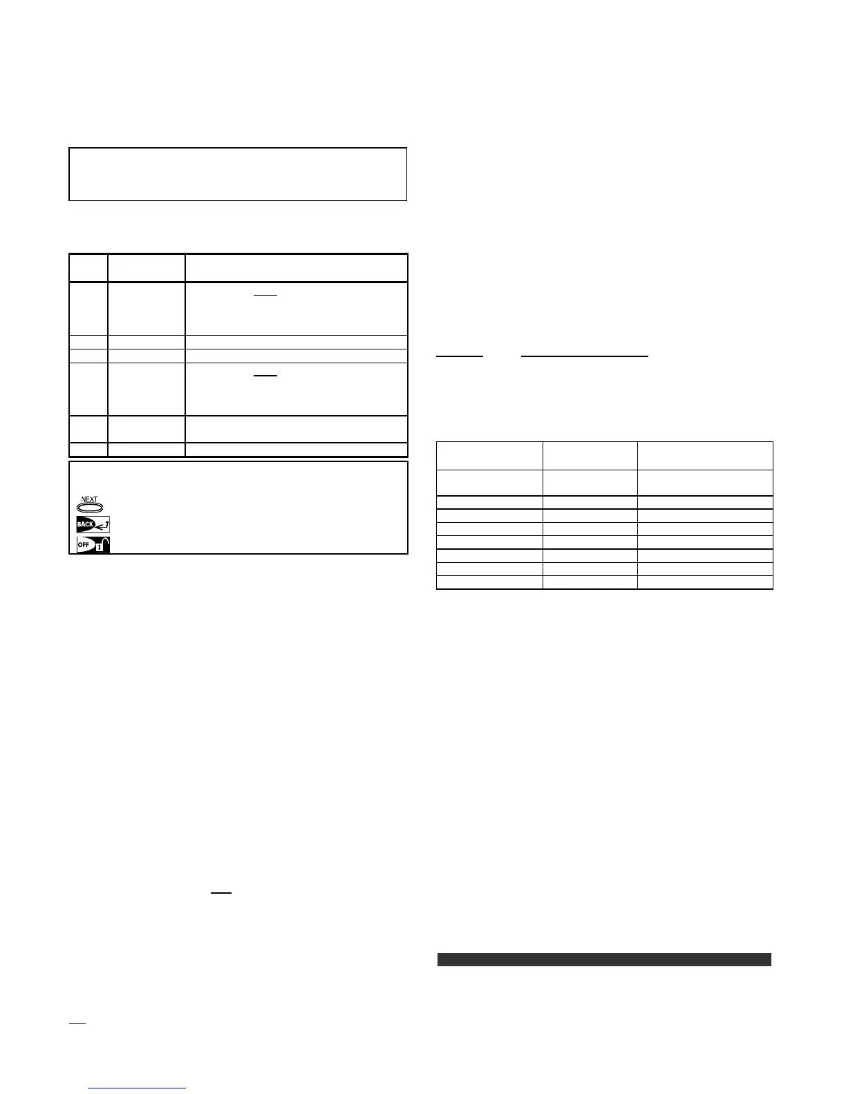
IMPORTANT: In telephone / pager number locations and
account number locations, you may be required to enter
hexadecimal digits. In telephone number locations, these
digits are used as codes to control the dialer:
Hex.
Digit
Keying
Sequence
Code
Significance
A <#>
⇒
<0> Applicable only at the beginning of a
number - the dialer waits 10 seconds
or waits for dial tone, whichever
comes first and then dials.
B <#>
⇒
<1> Inserts an asterisk (J)
C <#>
⇒
<2> Inserts a pound sign (#)
D <#>
⇒
<3> Applicable only at the beginning of a
number - the dialer waits 5 seconds
for dial tone and goes on hook if none
is received.
E <#>
⇒
<4>
pplicable only in the middle of the
number - the dialer waits 5 seconds
F <#>
⇒
<5> Not applicable in phone numbers
To enter a series of digits, use the following keys:
<Numeric keypad> - to enter the number
- moves the cursor from left to right
- moves the cursor from right to left
- deletes everything after the cursor (to the right).
4.5.1 Autotest Time (fig. 4.5, location 01)
Here you determine the time at which the telephone line
will be tested and reported to the central station.
4.5.2 Autotest Cycle (fig. 4.5, location 02)
Here you determine the time interval between consecutive
telephone line test messages sent to the central station.
The control panel performs this at regular intervals to verify
proper communications.
The options are: test every 1, 5, 7, 14, 30 days and test off.
4.5.3 Area Code (fig. 4.5, location 03)
Here you enter the system tel. area code (up to 4 digits).
4.5.4 Out Access No (fig. 4.5, location 04)
Here you enter the number that is used as a prefix to
access an outside telephone line (if exists).
4.5.5 First Central Station Tel. (fig. 4.5, loc. 05)
Here you program telephone number of the 1
st
central station
(including area code, 16 digit max) to which the system will
report the event groups defined in memory location 11 (see
note in fig. 4.5).
4.5.6 First Account No. (fig. 4.5, location 06)
Here you enter number that will identify your specific alarm
control system to the first
central station. The number
consists of 4 or 6 hexadecimal digits (see note in fig. 4.5).
4.5.7 2
ND
Central Station Tel. (fig. 4.5, loc. 07)
Here you program telephone number of the 2
nd
central station
(including area code, 16 digit max) to which the system will
report the event groups defined in memory location 11 (see
note in fig. 4.5).
4.5.8 Second Account No. (fig. 4.5, loc. 08)
Here you enter number that will identify your system to the
2
nd
central station. The account number consists of 4 or 6
hexadecimal digits (see note in fig. 4.5).
4.5.9 Report Format (fig. 4.5, location 09)
Here you select the reporting format used by the control panel
to report events to central stations (see note in figure 4.5).
The options are: Contact-ID SIA 4/2 1900/1400
4/2 1800/2300 Scancom (see Appendix C - code lists).
4.5.10 4/2 Pulse Rate (fig. 4.5, location 10)
Here you select the pulse rate at which data will be sent to
central stations if any one of the 4/2 formats has been
selected in Location 09 REPORT FORMAT (see note in
fig. 4.5). The options are: 10, 20, 33 and 40 pps.
4.5.11 Reporting to Central Stations
(fig. 4.5, location 11) (see note in fig. 4.5).
Here you determine which types of event will be reported
to central stations. Due to lack of space in the display,
abbreviations are used: alarm is “alrm”, alert is “alrt” and
open/close is “o/c”. The asterisk (J) is a separator
between events reported to central station 1 and events
reported to central station 2.
Messages are divided by type into three groups:
GROUP
EVENTS REPORTED
Alarms Fire, Burglary, Panic, Tamper
Open/Close Arming AWAY, Arming HOME, Disarming
Alerts No-activity, Emergency, Latchkey
"Alarm" group has the highest priority and "Alert" group
has the lowest priority.
The selectable options are as follows:
Plan name Sent to center
1
Sent to center 2
all -o/c J backup All but open/close All but open/close if center 1
doesn’t respond
all J all All All
all-o/c J all -o/c All but open/close All but open/close
all –o/c J o/c All but open/close Open/close
all (–alrt) J alrt All but alerts Alerts
Alrm J all (–alrm) Alarms All but alarms
Disable report Nothing Nothing
all J backup All All if cent. 1 doesn’t respond
Note: “All” means that all 3 groups are reported and also
trouble messages - sensor / system low battery, sensor
inactivity, power failure, jamming, communication failure etc.
4.5.12 Report CNF Alarm (fig. 4.5, location 12)
Here you determine whether the system will report whenever
2 or more events (confirmed alarm) occur during a specific
period (see par. 4.4.32 and note in figure 4.5).
Available
options are: enable report, disable report, enable
+ bypass (enabling report and bypassing the detector -
applicable to PowerMax+ that is compatible with DD423 standard).
4.5.13 Send 2WV Code (fig. 4.5, location 13)
Here you determine whether the system will send two-way
voice code to the central station (to turn the central station
from data communication to voice communication state) by
using pre-selected SIA or Contact-ID communication format
only (see note in fig. 4.5). Options: send and don't send.
4.5.14 Two-Way Voice Central Stations
(fig. 4.5, loc. 14). (See note in fig. 4.5).
Here you select the timeout for 2-way voice communication
with Central Stations, or enable the central station to ring
back for 2-way voice function. This option is applicable only
after reporting an event to the central station. (The central
station person can press [3] for listen-in", [1] for "speak out"
or [6] for listening and speaking).
The options are: 10, 45, 60, 90 seconds, 2 minutes, ring
back and disable (no two-way voice communication).
In UL installations, this function must be disabled.
Note: If "Ring Back" is selected, you should select "Disable
Report" for private telephone (see par. 4.5.20 - Reporting to
Private Telephones), otherwise the central station will
establish communication with the PowerMax+ (after an
event occurrence) in the normal manner (and not after one
ring).