DE5467IP 21
*** The currently saved option is displayed with a dark box at the right side. To review the options, repeatedly click NEXT button
until the desired option is displayed, then click OK (a dark box will be displayed at the right side). For zone name list, refer to
paragraph 4.3 (DEFINE ZONE TYPES).
Each X-10 unit has default zone name ( 01- front door, 02 - garage, 03 - garage door, 04 - back door, 05 – child room, 06 –
office, 07 – dining room, 08- dining room, 09 – kitchen, 10 – living room, 11 – living room, 12 – bedroom, 13 – bedroom, 14 –
guest room, 15 – master bedr).
OK
NEXT
X-10 GENERAL DEFDEFINE INT/STRB
NEXT
TRBL INDICATION
OK
OK
don’t indicate
indicate
FAIL REPORT
OK
NEXT
X-10 UNIT DEFINE
NEXT
NEXT
DEFINE PGM
NEXT
FLASH ON ALARM
OK
NEXT
report to PAGERreport to C.S. 2
NEXT
rep to private
NEXT
report to C.S. 1
NEXT
send SMS
OK
no flash
OK
all light flash
OK
OK
OK
disable
OK
enable
disable
OK
enable
OK
disable
OK
enable
OK
disable
OK
enable
NEXT
disable
enable
3 PHASES & FREQ
OK
NEXT
LOCKOUT TIME
OK
NEXT
start - HH:MM A
stop - HH:MM A
xxxx - 00:00 A
OK
OK
disable 3 phase
OK
3 phase 50 Hz
3 phase 60 Hz
Select “start”/”stop”and
enter the desired time.
Figure 4.8 - Detail A
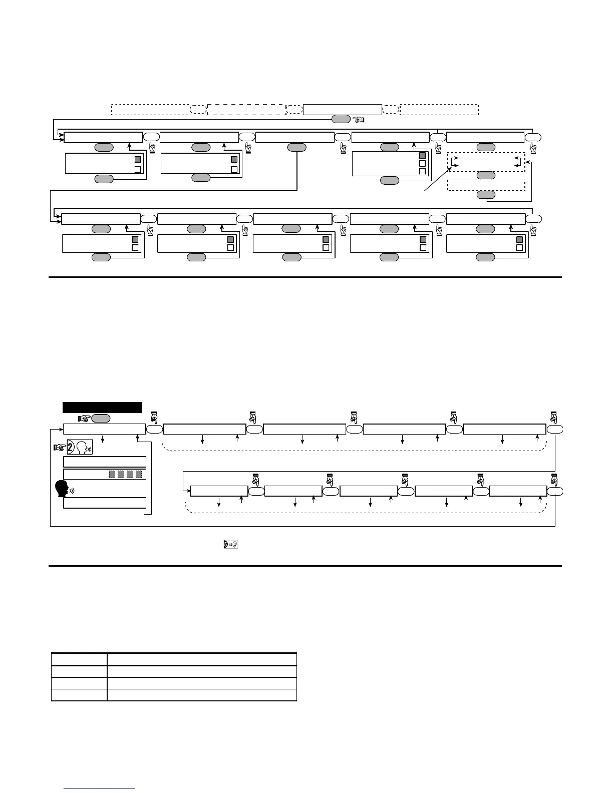
4.9 RECORDING SPEECH
This mode allows you to record short-duration speech
messages for the following purposes:
• House identity is a message announced automatically
when events are reported to private telephones.
• 4 User Names can be recorded and assigned to users
numbered 5-8. In case of event, the relevant user
name will be added to the message that will be
reported via the telephone.
• 5 custom zone names can be recorded and assigned
to specific zones. These names are useful if none of
the 26 fixed zone names are found suitable for a
certain zone (see fig. 4.3).
The recording process is shown below.
NEXT
OK
HOUSE IDENTITY
9. RECORD SPEECH
(see figure 4.1a)
USER #5 NAME
NEXT
USER #6 NAME
NEXT
USER #7 NAME
NEXT
USER #8 NAME
RECORDING ENDED
TALK NOW
RECORD A MESSAGE
(e.g. “John’s house”)
(*) (*)
NEXT
(*) RECORD MESSAGE is displayed momentarily. The dark square boxes slowly disappear, one by one, until end of recording time.
(**) To check the recorded message, press the key and listen to the playback.
- don’t release
Release button [2]
(**)
Record users 5 - 8 names (for example, David, Rose, Mark, etc.).
The process is identical to HOUSE IDENTITY recording process.
USER TERM #1 USER TERM #2 USER TERM #3 USER TERM #4 USER TERM #5
NEXT NEXT NEXT NEXT NEXT
Record users terms 1-5 (e.g. Living room, Library, etc.), identical to HOUSE IDENTITY recording process.
Figure 4.9 - Speech Recording Flow Chart
4.10 DIAGNOSTIC TEST
This mode allows you to test the function of all protected
area wireless sensors / wireless sirens and to receive /
review information regarding the received signal strength.
Three reception levels are sensed and reported:
Received Signal Strength Indication
Reception Buzzer Response
Strong Happy Tune twice ( - - - –––– ) ( - - - ––––)
Good Happy Tune ( - - - –––– )
Poor Sad tune ( –––––––– )
The diagnostic test process is shown in figure 4.10.
When you are instructed to perform "walk test", walk
throughout the site to check the detectors / sensors. When
a detector/sensor is triggered into alarm, its name, number
and the alarm reception level should be indicated (for
example, "Bathroom", "Z19 strong") and the buzzer should
sound according to the alarm reception level (1 of 3).
IMPORTANT! Reliable reception must be assured.
Therefore, a "poor" signal strength is not acceptable. If
you get a "poor" signal from a certain detector, re-locate it
and re-test until a "good" or "strong" signal strength is
received. This principle should be followed during the initial
testing and also throughout subsequent system
maintenance.
For UL installation, the test result must be STRONG
for all wireless devices.