DE5467IP 19
4.6.4 GSM Line Failure Reporting
Here you determine whether GSM network failure will be
reported after 2 min., after 5 minutes, after 15 min., or after
30 minutes. Available options: don't report, 2 min, 5 min,
15 min, or 30 min.
4.6.5 GSM Line Purpose
Define whether the GSM unit will serve as a backup for the
regular telephone line, as a primary communication
channel or as the only telephone channel or for sending
SMS only. Available options are: GSM is backup, GSM is
primary, GSM only or SMS only.
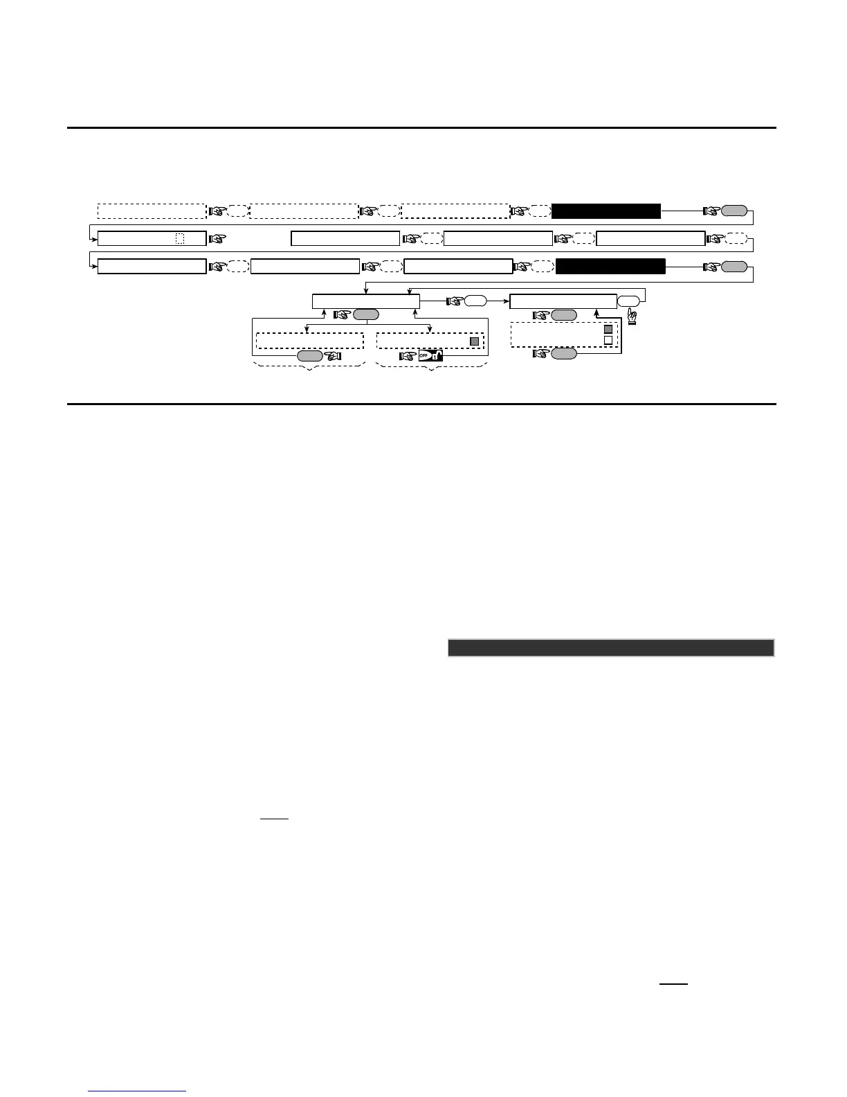
4.7 DEFINING POWERLINK
This mode enables you to enroll/delete the PowerLink
(PowerMax+ Web based remote controller) and to
enable/disable PowerLink failure reporting. The process is
as follows (for EN compliance installer mode is accessed
through the user menu):
INSTALLER MODEUSER SETTINGSNORMAL MODE
READY 00:00
NEXT NEXT
OK
NEXT
3. DEFINE ZONES2. ENROLLINGENTER CODE
[installer code]
1. NEW INSTL CODE
NEXT NEXT NEXT
5. DEFINE COMM.4. DEFINE PANEL 7. DEFINE PWRLNK
NEXT NEXT
6. DEFINE GSM
NEXT
NEXT
NEXT
OK
2: PWRLNK FAILURE
OK
disable report
report
<OK> to enroll
OK
<OFF> to delete
OK
1: INSTALL
Deleting PowerLink
Enrolling PowerLink
Note: Enrolling success
is accompanied by a
confirmation sound.
OK
Figure 4.7 - DEFINE POWERLINK
4.8 DEFINING OUTPUT PARAMETERS
4.8.1 Preliminary Guidance
This mode allows you:
a. Events/conditions selection under which PGM (programmable)
output and fifteen “X-10” devices will function.
b. Function type selection for every X-10 unit and PGM output.
c. General definitions selection for X-10 units
d. Selection of the internal siren or STROBE light (that will
be activated according to system programming).
e. Enrolling 2-way X-10 units.
The process is shown in Fig. 4.8. Each selected option is
displayed with a dark box at the right side. To review the
options, repeatedly click NEXT or BACK button, until the
desired option is displayed, then click SHOW/OK button.
4.8.2 Define PGM
For the PGM output, you can select disable, turn on, turn
off or pulse active (turn on for predefined period, selected
by PULSE TIME), as follows:
BY ARM AWAY (upon AWAY arming).
BY ARM HOME (upon HOME arming).
BY DISARM (upon disarming).
BY MEMORY (activated upon registration of an alarm in
the memory, turned off upon memory clearing).
BY DELAY (during exit / entry delays).
BY KEYFOB (upon AUX button pressing in the keyfob
transmitter / MCM-140+, if “PGM/X-10” is selected in
“Define Panel” menu, location 17).
BY ZONES (by disturbance in each
of 3 selected zones,
irrespective of arming / disarming). If you select toggle,
the PGM output will be turned on upon event
occurrence in these zones and will be turned off upon
next event occurrence, alternately.
BY LINE FAIL: PGM output is ON if telephone line is
disconnected.
4.8.3 Defining INT/STRB
Here you determine whether the INT output will be used for an
internal siren or for a strobe. If strobe is selected, the INT
output will be activated when an alarm occurs until the system
is disarmed and rearmed again (i.e. clearing alarm memory).
4.8.4 X-10 GENERAL DEF (Not evaluated by UL)
For X-10 devices, you can select the following actions:
FLASH ON ALARM (you can select no flash or all light
flash, to control X-10 lighting devices in alarm conditions).
Applicable only for X-10 lamp module - not applicable for
appliance module.
TRBL INDICATION (you can select don't indicate or
indicate for X-10 failure indication by the TROUBLE LED).
FAIL REPORT (You can select report to central station 1,
report to central station 2, report to pager, report to private
telephone and send SMS, for X-10 devices failure reporting).
3 PHASES & FREQ (you can select disable 3 phase, 3
phase 50 Hz, or 3 phase 60 Hz to define the X-10 signal
transmission type).
LOCKOUT TIME (You can enter daytime limits between
which X-10 lighting devices controlled by sensors will be
off, even when the associated sensors are triggered).
To disable lockout time the START and STOP times
should be identical (see figure 4.8 detail A).
In UL installations, this function shall not be used.
4.8.5 X-10 UNIT DEFINE (Not evaluated by UL)
For the fifteen X-10 units you can perform the following
programming actions:
a. House code selection (a code letter from A to P that will
distinguish the site in which the system is installed from
other sites in the neighborhood).
b. Specific number definition for every X-10 unit (01 – 15).
c. Enrolling 1-way X-10 units
d. Enrolling 2-way X-10 units (that can perform status reporting).
Note: If a 2-way X-10 unit is installed without enrolling,
interference to the 1-way X-10 units operation may occur.
e. For each X-10 unit you can select disable, turn on, turn
off or pulse active (turn on for predefined period, selected
by PULSE TIME), upon the following conditions:
BY ARM AWAY (upon AWAY arming).
BY ARM HOME (upon HOME arming).
BY DISARM (upon disarming).
BY MEMORY (activated upon registration of an alarm in
the memory, turned off upon memory clearing).
BY DELAY (during exit / entry delays).
BY KEYFOB (upon AUX button pressing in the
keyfob transmitter / MCM-140+, if “PGM/X-10” is
selected in “Define Panel” menu, location 17).
BY ZONES (by disturbance in each
of 3 selected
zones, irrespective of arming / disarming). If you
select toggle, the PGM output will be turned on upon
event occurrence in these zones and will be turned
off upon next event occurrence, alternately.