DE5467IP 7
f. A minimum spacing of 1/4 inch shall be maintained
between the telephone wiring and the low voltage
wiring (zones, bell circuit, etc). Do not route the LINE
and SET wires in the same wiring channel with other
wires.
g. The "V+" terminal should not be used in UL
installations.
3.6 Connecting the AC Transformer
CAUTION! Do not plug the transformer into the AC
outlet before completing all other wiring.
A. U.S.A. only: Remove the center screw from the AC wall
outlet.
B. Plug the transformer directly in - the Power LED of the
control panel should illuminate.
C. U.S.A. only: Use the screw removed in Step A above
to secure the transformer to the AC outlet. Tighten the
screw well.
D. The distance of the transformer from the system should
not exceed 150 ft using 18 AWG conductors.
For UL installations, do not connect to a receptacle
controlled by a switch.
3.7 Installing an Optional X-10 Siren
(Not to be used in UL-listed systems)
If you need a “wireless” external siren, you may install an X-
10 siren module which is triggered by a signal transmitted
via the built-in electrical wiring of the protected site. This
siren can replace the regular external siren or complement
it without laying out additional wires. Of course, such a siren
can be used only in conjunction with an optional power-line
interface module.
The X-10 siren is ready to function upon connection to an
electrical power outlet, without re-programming the Power-
Max+. You only have to set the HOUSE CODE and the
UNIT CODE selectors on the X-10 siren as follows:
House Code: Set this selector to the letter that follows, by
alphabetical order, the letter that you programmed as a
house code for the protected premises. For example, if the
programmed house code is “J”, set the siren house code
selector to “K”.
Note: If the programmed house code letter is “P” (which is
the last programmable letter), select “A” for the siren.
Unit Code: The siren will function only if you set the unit
code selector to “1”.
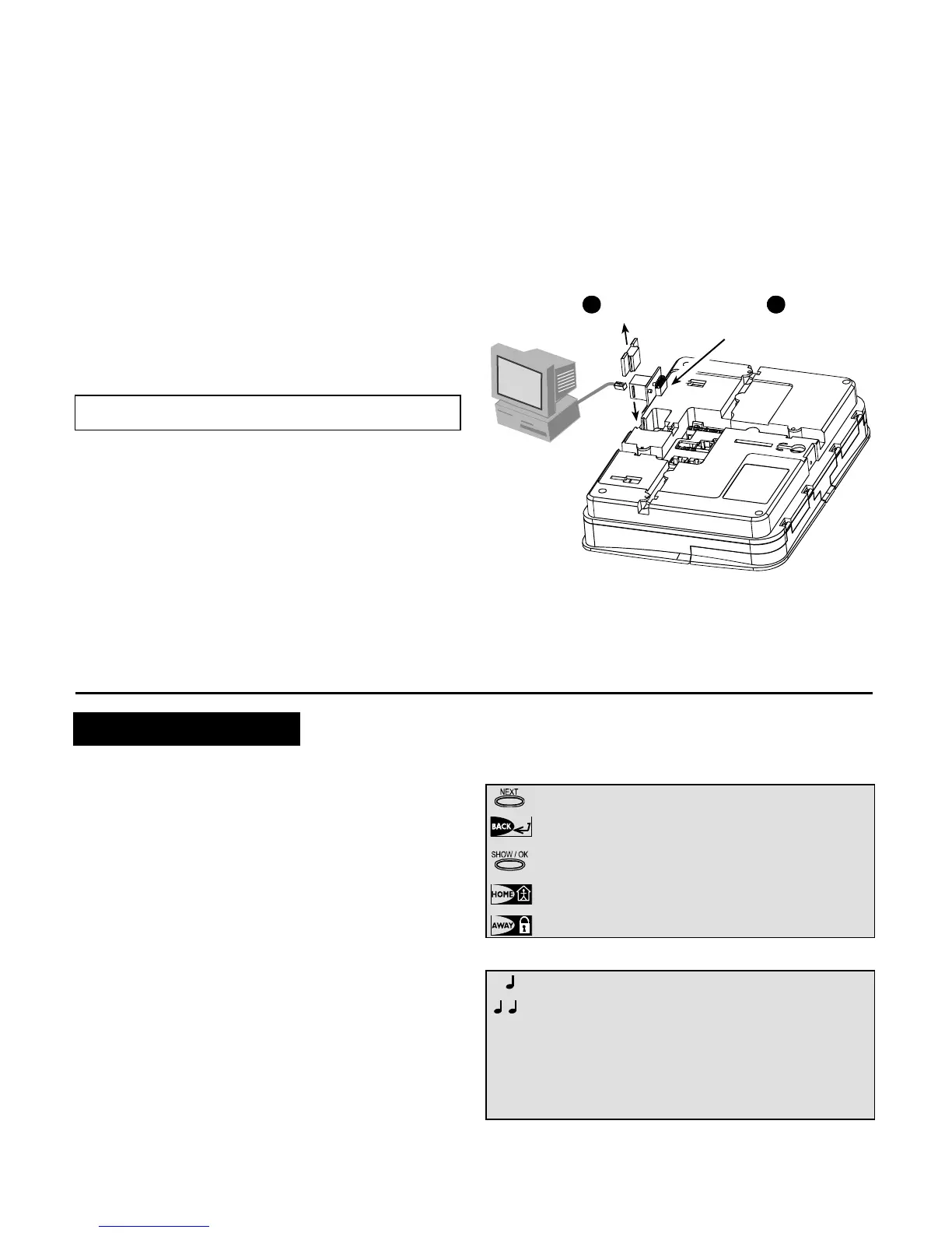
3.8 Connecting PowerMax+ to Computer
The control panel can be equipped with an optional RS232
module for serial data interchange with a local computer. If
this module is not supplied, a special plastic cap blocks the
niche designed to accommodate the module.
RJ-45
or
RJ-31X
(USA)
1
Remove
plastic
cap
Insert the RS-232
adapter into its male
connector, until a click
is heard
2
Figure 3.4 - Connecting the PowerMax+ to a Computer
3.9 Connecting PowerMax+ to GSM Modem
The GSM unit enables the PowerMax+ system to operate
over a cellular network. For details regarding the GSM
modem features and connections, refer to the GSM
Modem installation instructions.
4. PROGRAMMING
4.1 INTRODUCTION
4.1.1 General Guidance
We recommend to program the PowerMax+ on the work
bench before actual installation. Operating power may be
obtained from the backup battery or from the AC power supply.
The installer’s menu is accessible only to those who know
the installer’s 4-digit code, which is 9999 by factory default.
Note: Access to the installer menu, in PowerMax+ that has
"User Permission" enabled (for example in UK) is
accessible only at the end of the user menu. This option
can be changed is necessary (see par. 4.4.35).
For PowerMax+ that has 2 installer codes (not applicable
in UK), the default INSTALLER code is 8888 and the
default MASTER INSTALLER code is 9999.
The following actions can be done only by using the
master installer code:
• Changing master installer code.
• Resetting the PowerMax+ parameters to the default
parameters,
• Defining specific communication parameters, as
detailed in a note in figure 4.5.
Obviously, you are expected to use this code only once for
gaining initial access, and replace it with a secret code
known only to yourself.
You will mainly use 5 control pushbuttons during the entire
programming process:
- to move one step forward in a menu.
- to move one step backward in a menu.
- to enter the relevant menu or confirm data.
- to move one level up in a menu.
- to return to the "OK TO EXIT" state.
The sounds you will hear while programming are:
- Single beep, heard whenever a key is pressed.
- Double beep, indicates automatic return to the
normal operating mode (by timeout).
☺
- Happy Melody (- - - –––), indicates successful
completion of an operation.
- Sad Melody (–––––), indicates a wrong move
or rejection.