4 DE5467IP
Current Drain: Approx. 65 mA standby, 800 mA at full
load and in alarm.
Site External Siren Current (EXT): 550* mA max @ 10.5
VDC when powered by AC & DC (battery).
Site Internal Siren Current (INT): 550* mA max. @ 10.5
VDC when powered by AC & DC (battery)
PGM Output Current: 100* mA max.
Detector 1 & 2 Total (Sum) Current: 100* mA max.
High Current / Short Circuit Protection: All outputs are
protected (current limited).
* Total PowerMax+ output current (of INT & EXT sirens,
PGM output and detectors) cannot exceed 550 mA. For UL
installations, total output current cannot exceed 400 mA.
For EN installations, no external loads can be connected
to the PGM output and detector output.
Backup Battery Pack
(The exact configuration is according to the purchase
option – see sticker on battery cover):
Standard
installations
(Provides backup for up to 12 hours):
7.2V 1300 mAh, rechargeable NiMH
battery pack, p/n GP130AAM6YMX,
manufactured by GP.
UK
installations
(Provides backup for up to 12 hours):
9.6V 1300 mAh, rechargeable NiMH
battery pack, p/n GP130AAM8YMX,
manufactured by GP.
UL
installations
(Provides backup for up to 24 hours):
Rechargeable NiMH battery pack 7.2V
2100 mAh p/n GP211ATH6XML, or 7.2V
2200mAh p/n GP220AAH6YMX,
manufactured by GP, trickle charge 80
mA approx.
Note: Other backup power period is available, up to 24 hours
Maximum Battery Recharge Time: 48 hours
Battery Test: Once every 10 seconds.
2.4 Communication
Built-in Modem: 300 baud, Bell 103 protocol
Data Transfer to Local Computer: Via RS232 serial port
Report Destinations: 2 central stations, 4 private
telephones, 1 pager.
Reporting Format Options: SIA, Pulse 4/2 1900/1400 Hz,
Pulse 4/2 1800/2300 Hz, Contact ID, Scancom.
Pulse Rate: 10, 20, 33 and 40 pps - programmable
Message to Private Phones: Tone or voice
Message to Pager: PIN No
.Alarm Type Zone No.
2.5 Physical Properties
Operating Temp. Range: 32°F to 120°F (0°C to 49°C)
Storage Temp. Range: -4°F to 140°F (-20°C to 60°C)
Humidity: 85% relative humidity, @ 30°C (86°F)
Size: 10-13/16 x 8 x 2-1/8 in. (275 x 203 x 55 mm)
Weight: 990g (2.2 pounds) without batteries
Color: Ivory and charcoal gray
3. INSTALLATION
3.1 Unpacking the Equipment
Open the cardboard packing box and check whether all
items have been included. If you find out that an item is
missing, contact your vendor or dealer immediately.
3.2 Supplying Power to the Unit
Enrolling the transmitting devices’ ID codes in the Power-
Max+ memory will be easier if carried out before actual
installation, with all detectors and the control panel on a
work bench. It is therefore necessary to power up the
PowerMax+ temporarily from the external power trans-
former (see figure 3.3). Alternatively, you may power up
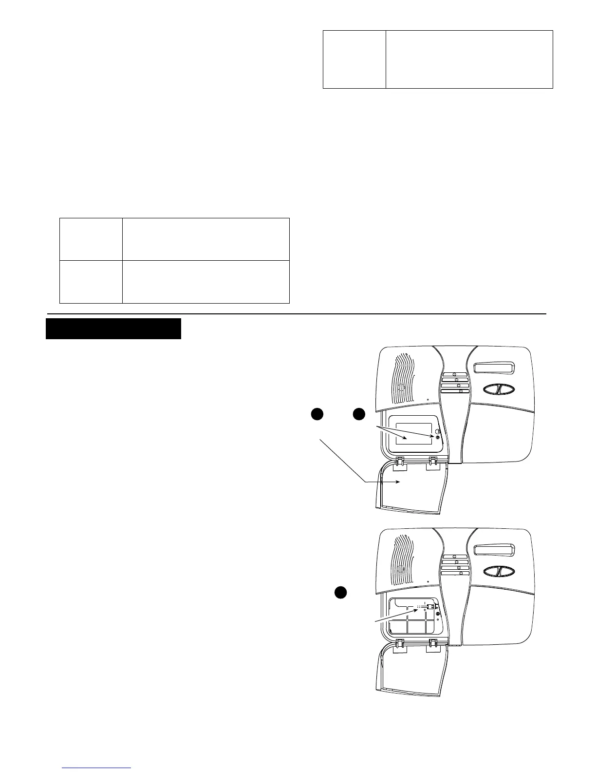
from the backup battery, as shown in figure 3.1.
Disregard any “trouble” indications pertaining to lack of
battery or lack of telephone line connection.
3.3 System Planning & Programming
It pays to plan ahead - use the tables in appendices A and
B at the end of this guide to register the intended location
of each detector, the holder and assignment of each
transmitter and the control plan for the X-10 units.
Gather up all transmitters and detectors used in the
system and mark each one in accordance with your
deployment plan.
Program the system now as instructed in the
programming section.
3.4 Mounting
Required tool: Philips screwdriver #2.
PowerMax+ mounting process is shown in figure 3.2.
3.5 Wiring
Required tools: Cutter and slotted screwdriver - 3mm blade.
PowerMax+ wiring is shown in figure 3.3.
Extract the screw terminal blocks one by one and make
the necessary connections. When done, plug each
terminal block onto its PCB mounted pins.
Open
door
1 2
Remove
screw
and cover
Connect
rechargeable
battery pack (see
sticker on battery
cover) to the battery
connector. Then
remount the cover
and close the door.
3
Figure 3.1 - Backup Battery Insertion