™
Page 17 of 81
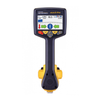
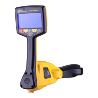
3 vLoc3-Pro Receiver
Sonde Specic mode for detecting and locating sonde transmitters.
Vector
conguration
Shows a cross section of the ground and line position relative to the locator.
Plan view Gives a plan view as if looking into the ground.
Trans. Graph
Shows a graphical representation of the peak and null field shape over a line (Active
modes only) Good for analysing signal distortion.
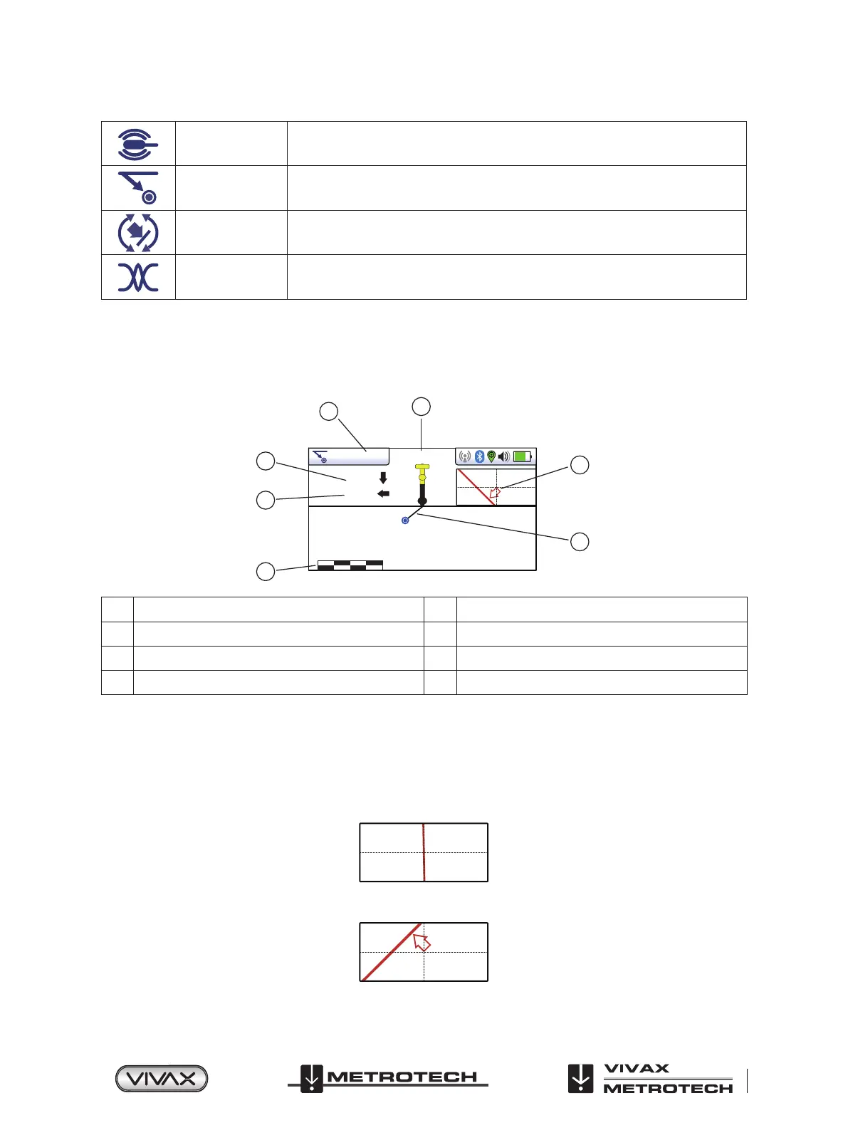
Vector Screen
The Vector Screen shows a cross sectional view through the ground. A plan view is also shown to help orientate the user
over the line. The Vector Screen is particularly useful where access directly over the line is not possible. Depth and horizontal
displacement distances are shown, even when not directly over the line.
8.19kHz
1.43m
1.86m
0 2m
85.6mA
3
2
1
6
7
4
5
1 Frequency selected 5 Scaling (adjust with +/- keys)
2 Signal current 6 Shows plan view of target
3 Vertical distance to target 7 Cross section view that shows vectors to target
4 Horizontal distance to target
Using the Vector screen
1. Apply the signal to the target line in the usual way and select the vector screen by using long presses on the “return” button
until the desired screen appears.
2. Position the locator within the approximate position of the target line. Use the plan view to help guide you towards the
target line. You can imagine that the plan view is giving you a view into the ground.
3. Position yourself so that the red target line is pointing forward/back and is centralized on the screen.
4. If the target is o the screen an arrow will appear on the screen to help direct you to the target line.
 Loading...