VIVOTEK - A Leading Provider of Multimedia Communication Solutions
User's Manual - 11
1 234 5 6 7 8 9 101112
WAN
POWER AC IN 100V-240V
LAN8
LAN7
LAN6
LAN5
LAN4
LAN3
LAN2
LAN1
RESET
Private LAN
Activity
Power/MIC
Activity
Power/MIC
x8
Router
DSL Modem
NVR embedded
DHCP server
Internet
LAN
Management
PC
1 234 5 6 7 8 9 101112
WAN
POWER AC IN 100V-240V
LAN8
LAN7
LAN6
LAN5
LAN4
LAN3
LAN2
LAN1
RESET
Activity
Power/MIC
Activity
Power/MIC
x8
Private LAN
NVR embedded
DHCP server
LAN
Management
PC
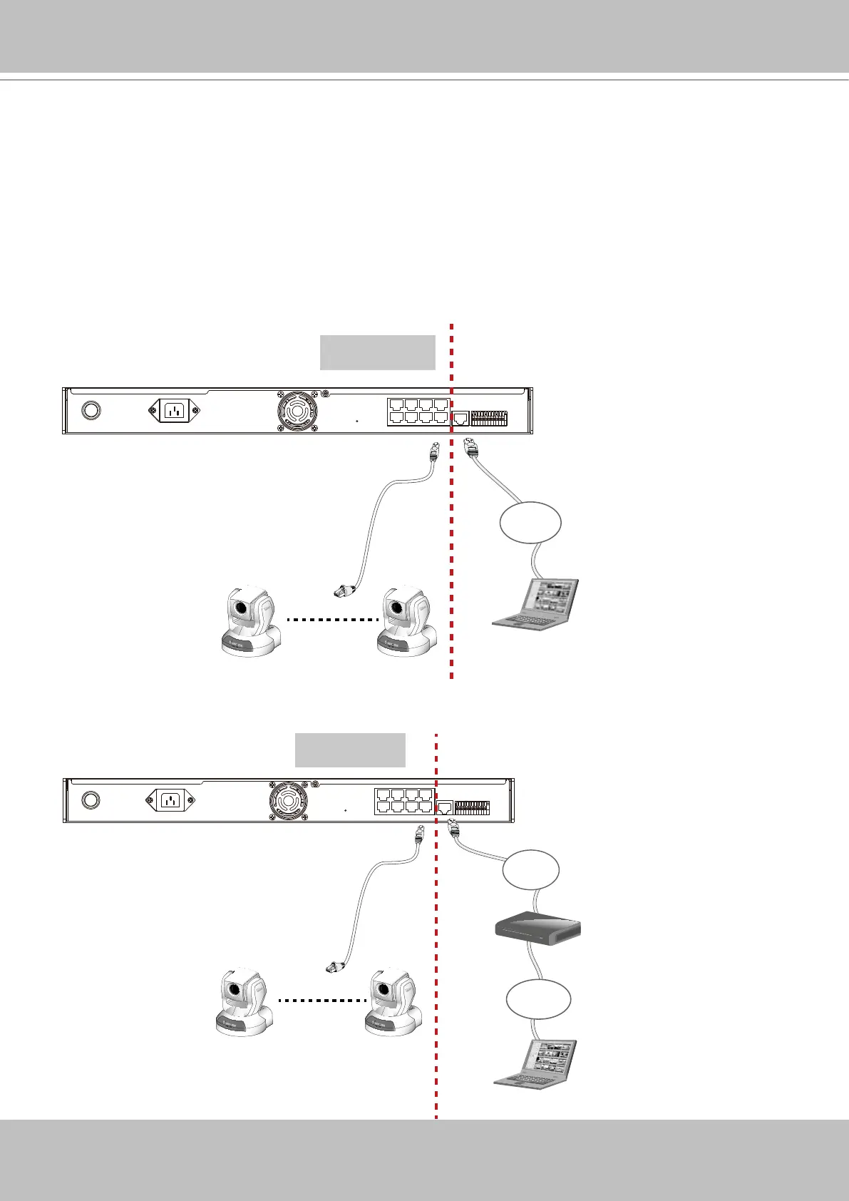
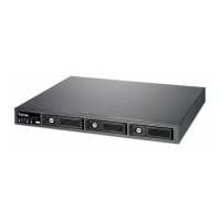
Supported & Unsupported Connections
1. You can connect a management PC to the NVR’s WAN port for management and monitoring.
All cameras should be connected to the 10/100BaseT “LAN” ports which reside on a different
subnet from the WAN port.
IMPORTANT!
Please configure the IP addresses for the “LAN” and “WAN” ports into different class C
subnets, e.g., 192.168.100.xxx for LAN and 192.168.4.104 for WAN. Make sure they are
not congured into the same subnet.
2. A remote PC can access the NVR via an Internet connection to the NVR’s WAN port. All cam-
eras should be connected to the 10/100BaseT “LAN” ports.