Release date 2016-05-15 23:28 Date of issue 2016-05-16 181005_eng.xml
KFD2-SOT2-Ex2
1
Refer to "General Notes Relating to Pepperl+Fuchs Product Information".
Pepperl+Fuchs Group USA: +1 330 486 0002 Singapore: +65 6779 9091Germany: +49 621 776 2222
www.pepperl-fuchs.com pa-info@us.pepperl-fuchs.com pa-info@de.pepperl-fuchs.com pa-info@sg.pepperl-fuchs.com
Switch Amplifier
Zone 2
Div. 2
Zone 0, 1, 2
Div. 1, 2
KFD2-SOT2-Ex2
24 V DC
14+
15-
Power Rail
24 V DCERR
7
8 (+/-)
9
I
II
2+
3-
1+
I
II
5+
6-
4+
10 kΩ
400 Ω ≤ R ≤ 2 kΩ
10 kΩ
10 kΩ
400 Ω ≤ R ≤ 2 kΩ
10 kΩ
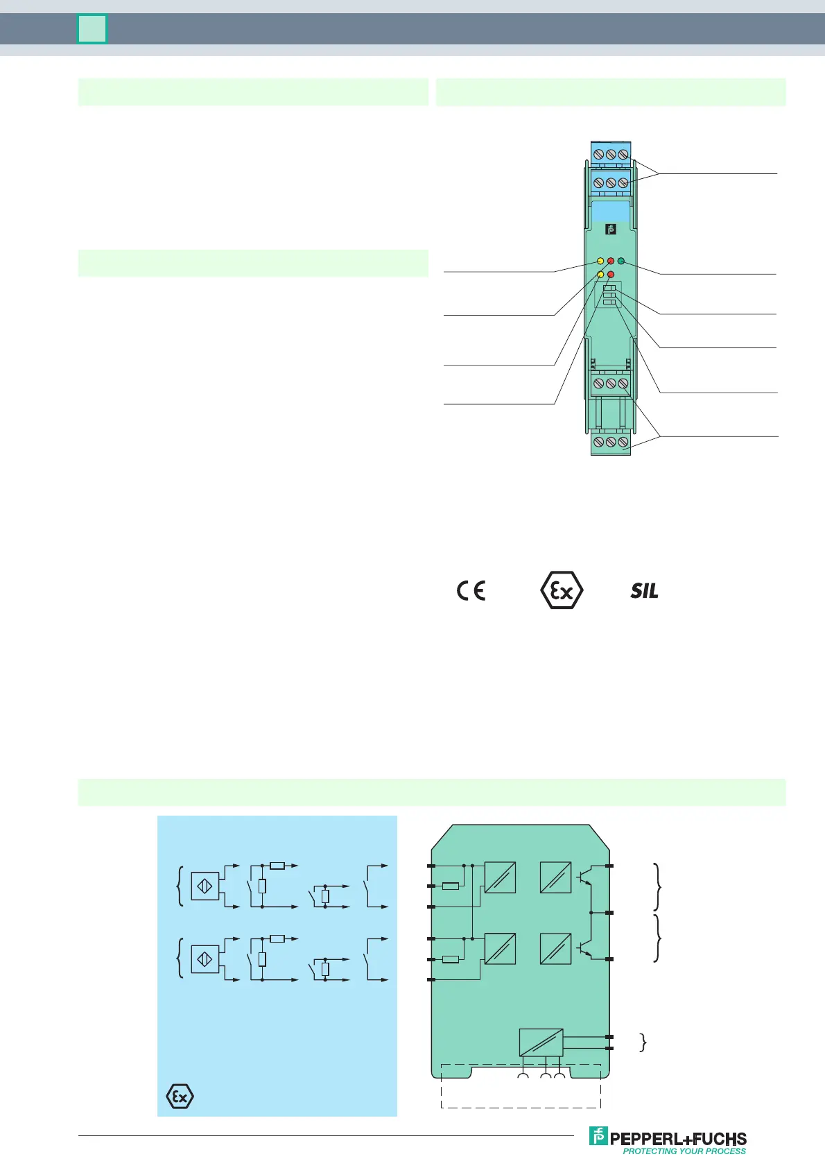
Connection
Assembly
• 2-channel isolated barrier
• 24 V DC supply (Power Rail)
• Dry contact or NAMUR inputs
• Passive transistor output, non-polarized
• Line fault detection (LFD)
• Reversible mode of operation
• Up to SIL 2 acc. to IEC 61508
Function
This isolated barrier is used for intrinsic safety applications. It
transfers digital signals (NAMUR sensors/mechanical
contacts) from a hazardous area to a safe area.
Each proximity sensor or switch controls a passive transistor
output for the safe area load. The normal output state can be
reversed using switch S1 for channel I and switch S2 for
channel II. Switch S3 enables or disables line fault detection of
the field circuit.
During an error condition, the transistors revert to their de-
energized state and LEDs indicate the fault according to
NAMUR NE44.
A unique collective error messaging feature is available when
used with the Power Rail system.
2
Features
1
3
4
6
2
5
13 15
12
9
10
7
14
11
8
KFD2-SOT2-Ex2
1
2
OUT CHK PWR
S2
S1
S3
III
Front view
LED yellow:
Transistor output I
LED yellow:
Transistor output II
LED green:
Power supply
Switch S1
(mode of operation channel I)
Switch S2
(mode of operation channel II)
Removable terminals
green
Removable terminals
blue
LED red:
LB/SC channel I
LED red:
LB/SC channel II
Switch S3
(LB/SC-monitoring)