6.Demonstration
Gain (db) = 20×log (gain)
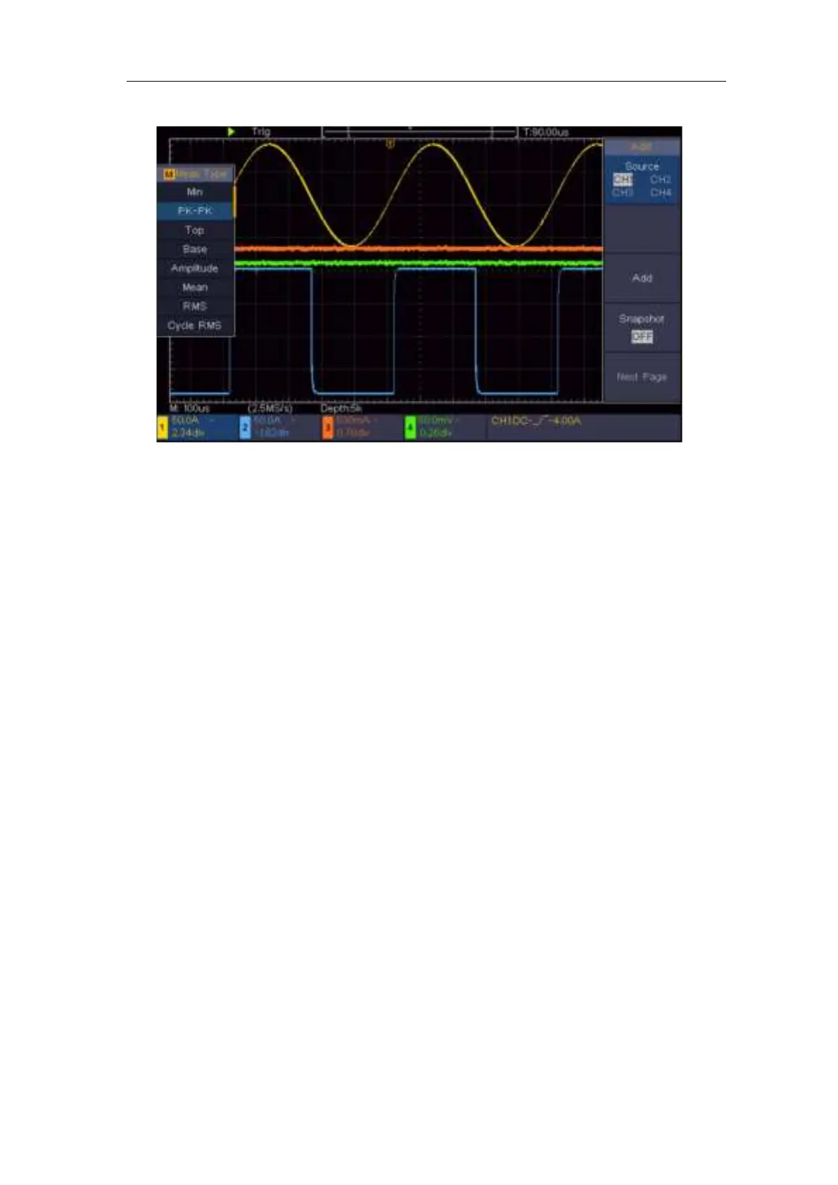
Figure 6- 2 Waveform of Gain Measurement
Example 3: Capturing a Single Signal
It's quite easy to use Digital Oscilloscope to capture non-periodic signal, such
as a pulse and burr etc. But the common problem is how to set up a trigger if
you have no knowledge of the signal? For example, if the pulse is the logic
signal of a TTL level, the trigger level should be set to 2 volts and the trigger
edge be set as the rising edge trigger. With various functions supported by our
Oscilloscope, user can solve this problem by taking an easy approach. First to
run your test using auto trigger to find out the closest trigger level and trigger
type, this helps user to make few small adjustments to achieve a proper trigger
level and mode. Here is how we achieve this.
The operation steps are as follows:
(1) Set the probe menu attenuation coefficient to 10X and that of the switch in
the probe to 10X (see "How to Set the Probe Attenuation Coefficient" on
P11).
(2) Adjust the Vertical Scale and Horizontal Scale knobs to set up a proper
vertical and horizontal ranges for the signal to be observed.
(3) Push the Acquire button to display the right menu.
(4) In the right menu, select Acqu Mode as Peak Detect.
(5) Push the Trigger Menu button to display the right menu.
(6) In the right menu, select Single as Edge.
(7) In the right menu, select Source as CH1.