5.
Check the wear on the valve guides (see "Check-
i
ng of valve guides") before the valve seats are
treated.
150
°
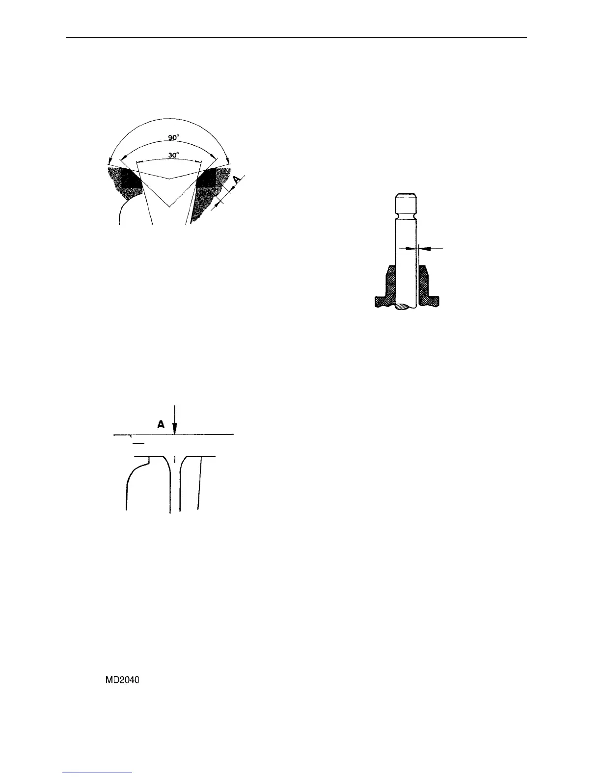
Fig. 20. Grinding of valve seat
A= Max. 2.5 mm (.0984 in)
6.
Ream or grind the valve seats (Fig. 20). Grind of
j
ust enough material so that the valve seat has the
right shape and a good mating surface.
lo
w
k
.A
Fig. 21. Checking of valve seat
Replace the valve seat when the distance "A" in Fig. 21,
measured with a new valve, exceeds 1.8 mm (.0708 in).
For replacement of the valve seat (inlet) see previous
page.
New seats are grind down so that the distance be-
t
ween the cylinder head plane and the valve disc
surface "A" is:
MD2O10, MD2020: 0.70-0.90 mm (.0275-.0354 in)
MD2030,
MD2040
:
0.85-1.15 mm (.0334-.0452 in)
7.
Grind in the valves with grinding paste and check
the contact with marker dye.
Engine body
8.
Fit the seals, valves, valve springs, spring washers,
valve lock and valve caps. See "Assembly of cylin-
der head" on page 31.
Checking of valve guides*
Fig. 22. Clearance, valve - valve guide (cylinder head)
Calculate the clearance between the valve spindle and
valve guide.
Wear tolerances:
I
nlet valve, max. clearance
0.20 mm (.0078 in)
Outlet valve, max. clearance
0.25 mm (.0098 in)
"
Note:
Since the valve guides are treated directly in the cylin-
der head this must be replaced when the clearance is exces-
sive, even when the valve is new.
2 9
 Loading...