Electrical system
I
nspection of the starter motor
Troubleshooting on the starter motor should be handed
over to an authorised electrical workshop which disposes
over the necessary test equipment.
1.
Test the rotor with respect to winding flash-over and
failure with the test equipment for this purpose.
Fig. 120. Checking of the commutator
2.
Check that the mating surfaces for the electric
brushes on the commutator are smooth and free
from dirt and oil. If the commutator is damaged or
burnt it can be polished with sandpaper No. 500 or
600.
Measure the commutator with a dial gauge. Max.
permissible radial distortion is 0.05 mm (.0019 in).
3.
Check that the commutator's insulation lies at least
0.2 mm (.0078 in) below the laminated surface. Cor-
rect if necessary. See Fig. 120.
4.
Check the linearity of the rotor. Brace the rotor be-
tween spikes and measure the radial distortion on
the rotor frame with a dial gauge. Max. permissible
radial distortion is 0.08 mm (.0031 in).
Note:
The radial distortion is half of the read value.
5.
Check the cogs on the starter gear. Replace dam-
aged gear. Check also the starter gear ring if the
gear is damaged.
Field winding
Check with a test instrument that there is no failure in the
winding. If the field winding is defective it should be re-
placed.
7 8
Assembly of the starter motor
Assembly is carried out in the reverse order to strip-
ping.
Connect + and - from a 12 V battery to the terminal on
the magnet and check that the starter gear is pushed
forward to the gear stop.
Fitting of the starter motor
1.
Place the starter motor in position in the flywheel
housing and tighten it.
2.
Connect the electric cables to the starter motor.
See the wiring diagram on page 80-86.
3.
Connect both battery leads.
Electrical components
Relay box with fuses
The A-version has two fuse blocks each with four fus-
es (15A) for plus (+) and minus (-) placed on the relay
box at left-hand rear side of the engine.
The B/C-version has one fuse block.
The fuses disconnect the current in the event of over-
l
oading.
Re-connect the electrical system of a fuse has blown
by moving the cable connection to the next contact.
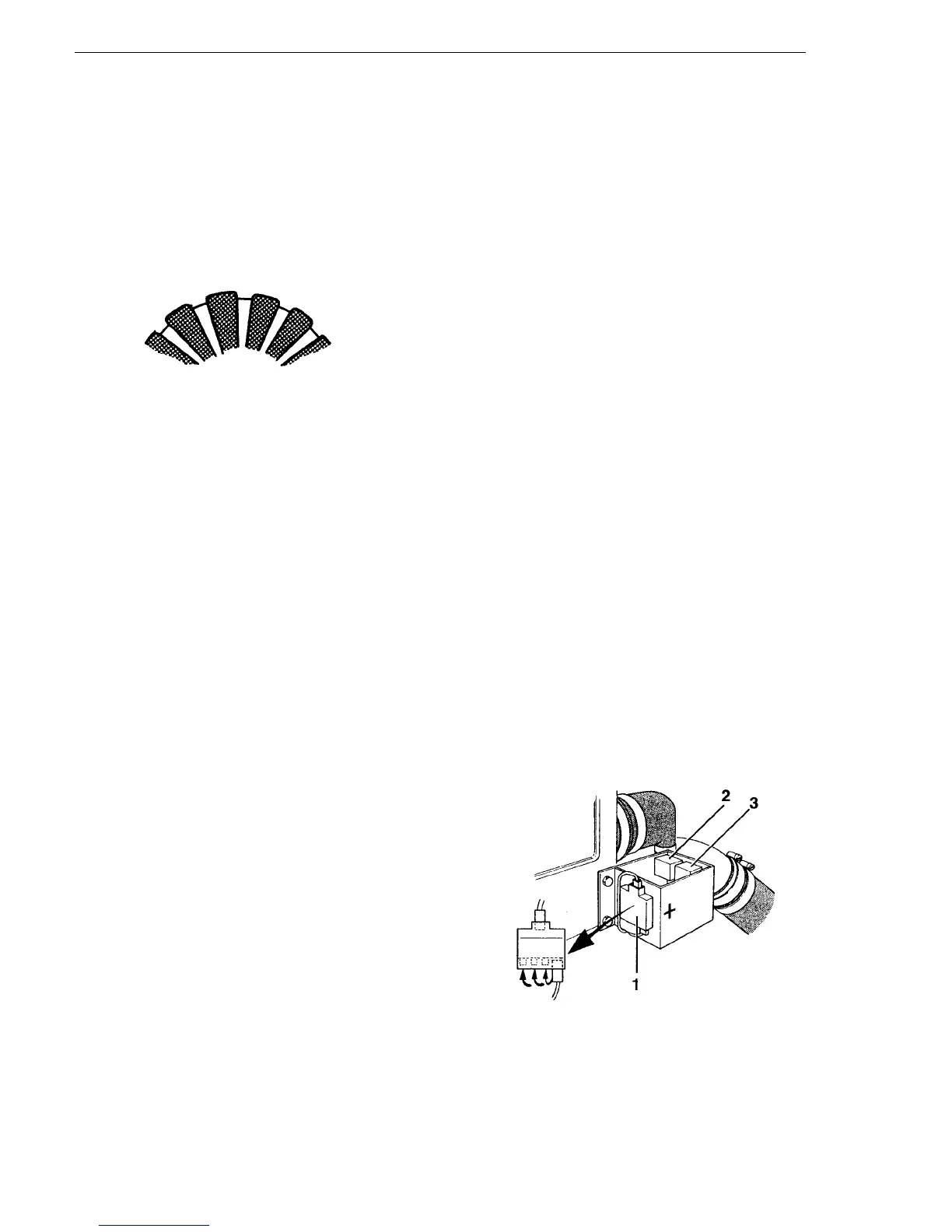
Fig. 121. Relay box with fuses
1.
Fuse block + (1 5A)
2.
Starter relay
3.
Glow relay