'
Engine body
14. Fit the sea water pump on the timing gear casing.
Connect the water hoses to the pump.
15. Fit the drive belt to the alternator.
Note: If the tension is correct the belt should be
able to be pressed in approx. 10 mm (.40
i
n)
be-
t
ween the pulleys.
16.
Open the fuel cocks. Bleed the fuel system as per
the directions on page 59.
17.
Connect the battery leads.
Camshaft
Dismantling the camshaft
1.
Dismantle the cylinder head. See "Dismantling of
cylinder head" on page 25. Lift out the valve lifters
and place them in order in a rack.
2.
Remove the timing gear casing. See under heading
"Dismantling of timing gear" on pages 40 and 41.
3.
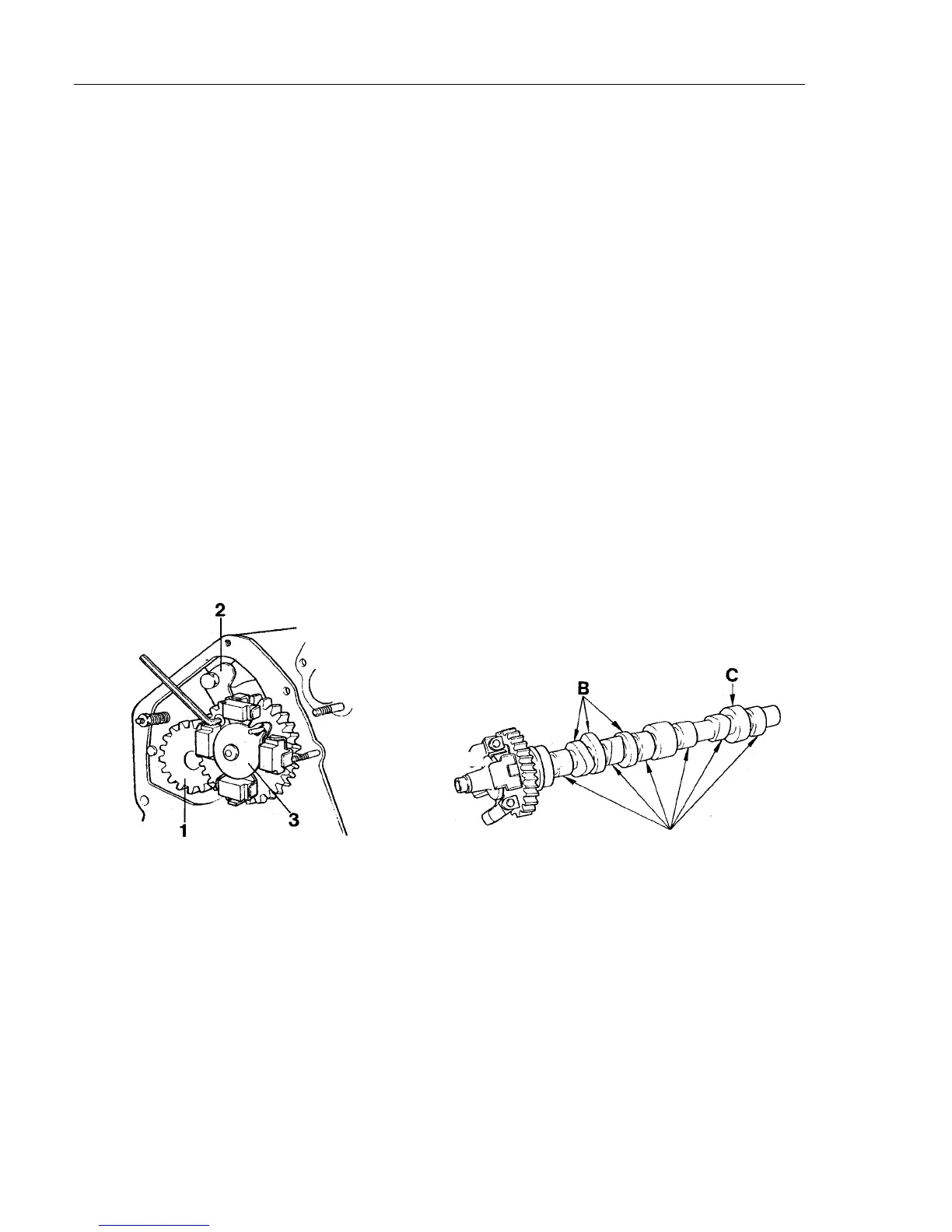
Remove the regulator sleeve from the camshaft.
4 4
Fig. 67. Dismantling of camshaft
1.
Gear
3.
Regulatorsleeve
2.
Lock washer
4.
Remove the screws for the lock plate (one screw is
accessible through the hole in the camshaft gear),
Fig. 67.
5.
Lift out the camshaft complete with gear and regu-
l
ator weights.
Note:
Observe care so that bearings, bearing races
or cams are not damaged.
On MD2030 and MD2040 the gear for the mechan-
i
cal tachometer drive* must be removed together
with the camshaft.
6.
MD2O10, MD2020: Remove the gear for the
mechanical tachometer drive*.
*
Note: Mechanical tachometer driving is not used by Volvo
Penta. The gear must, however, be in position.
I
nspection of valve lifter and camshaft
NOTE! If the lifter is worn over the lift surface the lifter
must be scrapped. The "dike" shows that the lifter has
not rotated. A dark stripe on the outer lift surface shows,
however, that the surface is not worn.
I
t is the condition of the valve lifters that determines
whether further checking of camshaft wear is
necessary.
The cam for example may be skew worn in an axial di-
rection. This can in less severe cases be adjusted by
grinding the cams. Replace the camshaft in the event of
further damage or wear.
Note:
When replacing the camshaft all the valve lifters
must be replaced.
Measuring the camshaft
to
A
Fig. 68. Measuring the camshaft.
Cam height (inlet and outlet) "A", Fig. 68.
MD2O10, MD2020, MD2030:
min. 26.1 mm
(1.027 in)
MD2040:
33.7 mm (1.326 in)
Cam height "B" (for injection pump)
MD2O10, MD2020:
min. 34.3 mm (1.350 in)
MD2030:
33.8 mm (1.330 in)
MD2040:
41.8 mm (1.645 in)
Cam height "C" (for feed pump)
MD2O10, MD2020, MD2030:
min. 27.0 mm
(1.062 in)
MD2040:
30.0 mm (1.181 in)
Replace the camshaft if the wear tolerances are not
maintained.


 To Next Page