Engine MD201OB/C, MD202OB/C, MD203OB/C, MD204OB/C
14
4
16
1
6
11
15 10
14
5 13
30
O
R25
86
30
85
87
0
R10
s6
12
R 2.5
1 1
1
VA
P
581o
5
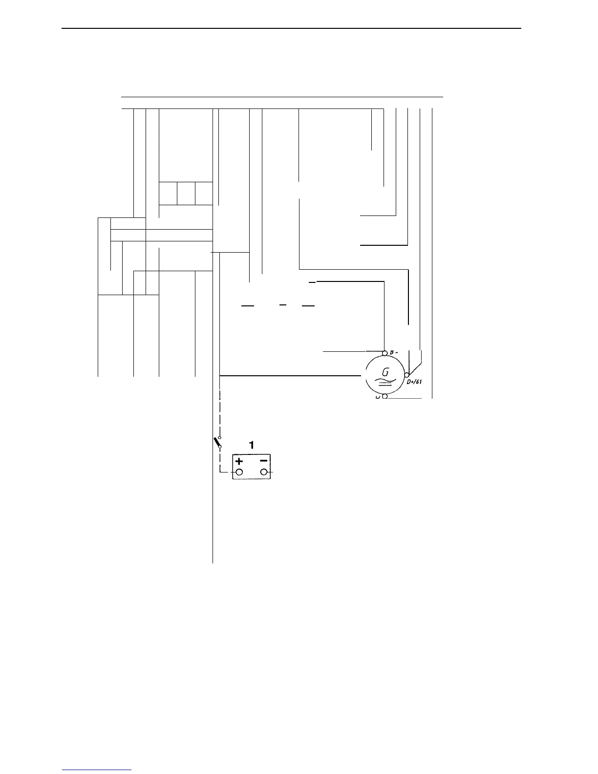
Cable areas in mm
2
are given after the colour code in the wiring diagram.
Areas not given = 1.0 mm
2
.
Dashed cables are not included from Volvo Penta.
11
10
2
3
3
m
m
Wiring diagram
MD2O10: 2 pcs. Other engines: 3 pcs
I
8
1
v
C)
0 n
C
R25
R25
s8
R/Y 2.5
30 87
86
-85
6
3
2
1.
Battery
7.
2.
Main switch
8.
3.
Starter motor
9.
4.
Alternator
10.
5.
Glow plug*
6.
Starter relay
11.
Cable colours
BL
=
Blue OR
Orange
LBL =
Light blue
R
Red
BN
=
Brown
SB
Black
LBN =
Light brown W
White
GN =
Green
Y
Yellow
GR =
Grey
Glow relay
12.
Refrigerant temperature relay (normally
Fuses (4 pcs), max. 15A (+)
open, closes at 100°C t2°C, 212°F t3.6°F)
Magnetising resistance (330/9W)
13.
Refrigerant temperature sensor
Oil pressure relay, engine (normally
14.
Connector, 16-pole
open, closed at 0.3 t0.1 bar)
Oil pressure sensor