Engine body
Fitting of cylinder head
1.
Clean the surface of the cylinder head and cylinder
block. Remove any rust or soot from the screw ho-
l
es and threads for the cylinder head screws.
2.
Fit on the new cylinder head gasket.
3.
Apply grease containing molybdenum disulphide
on the cylinder head screws.
NOTE! The screws are surface treated and must
not be cleaned with a steel brush.
Note:
I
f the cylinder head is painted the mating sur-
faces for cylinder head screws must be free from
paint, otherwise the clamping force in the screw
union will be adversely affected.
4.
Check that the tubular pins (guides) are fitted in the
block. Place the two rear cylinder head screws in
the cylinder head and fit the head.
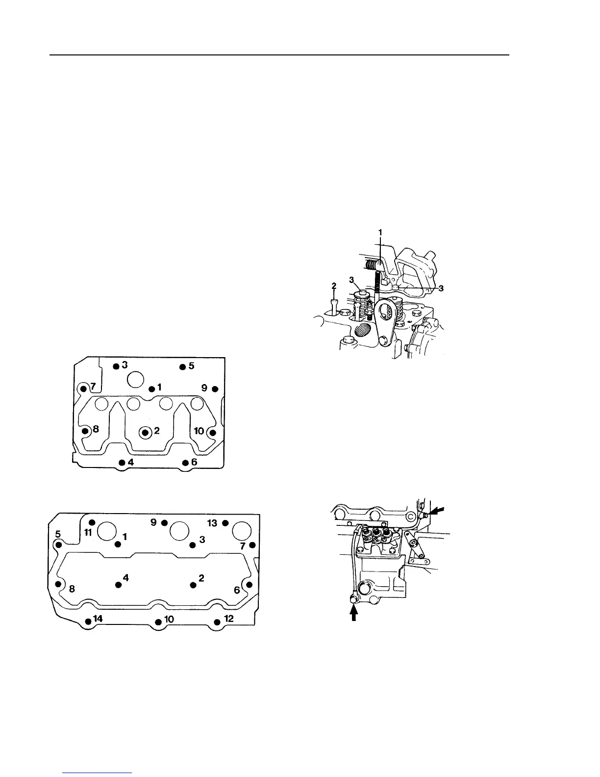
Fig. 30. Tightening diagram, MD2O10
Fig. 31. Tightening diagram MD2020, MD2030, MD2040
1st tightening
MD2O10. MD2020
10 Nm (7.40 ft.lbs)
MD2030
20 Nm (14.80 ft.lbs)
MD2040
30 Nm (22.10 ft.lbs
2nd tightening
MD2O10, MD2020
20 Nm (14.80 ft.lbs)
MD2030
35 Nm (25.80 ft.lbs)
MD2040
70 Nm (51.70 ft.lbs)
Final tightening
MD2O10, MD2020
35-40 Nm (26-30 ft.lbs)
MD2030
50-53 Nm (37-39 ft.lbs)
MD2040
90-95 Nm (66-70 ft.lbs)
Fig. 32. Fitting of the rocker mechanism (MD2040)
6.
Fit the pull rods (2), valve caps (3, MD2040 and
l
ater versions of 2010, 2020,2030) and rocker
mechanism (1).
7.
Adjust the valve clearance as per directions on
page 34. Fit the valve cover.
Fig. 33. Fitting of oil pressure pipe (cylinder block -
cylinder head / rocker mechanism)
e
8.
Fit the oil pressure pipe between the block and
5.
Tighten the cylinder head screws in three stages as
cylinder head (rocker mechanism on MD2040).
per the following. See tightening diagrams Fig. 30-
31.
Tightening torque 10-13 Nm (7.4-9.6 ft.lbs).
32