Fuses
The fuses are placed in the relay box at the rear left-
hand side of the engine. The fuses disconnect the cur-
rent when overloaded.
MD2010A, -2020A, -2030A and -2040A
are fitted with
two fuse blocks each with four fuses (15A) for plus (+)
and minus (-) .
MD201OB/C, -2020B/C, -2030B/C and -2040B/C
have
only one fuse block with four fuses (15A) for plus (+).
Re-connect the electrical system, after inspection and
work, if one fuse has triggered by moving the cable con-
nection to the next contact.
Relays
The relays are placed in the relay box on the rear left-
hand of the engine.
The start and glow functions are controlled via their own
switching relay. These relays are identical and therefore
i
f necessary can be interchanged.
Alternator
Voltage regulator with sensor system
The voltage regulator to the standard alternator (14V/
60A) is provided with a sensor system.
The sensor system compares the charge voltage be-
tween the alternator's connections B+ and 13- with that
between the batteries' plus and minus poles. The volt-
age regulator then compensates any voltage drop in the
cables between alternator and batteries by increasing
the charge voltage when necessary from the alternator.
On delivery from Volvo Penta the sensor system is not
activated. Connection has, however, in all probability
been carried out in connection with the installation of
the engine.
Electrical system
Connection of sensor system
0
I
mportant! Stop the engine and then switch off
the current with the main switches before
working on the electrical system.
1.
Release the yellow sensor conductor from connec-
tion B+ on the alternator.
2.
Splice the conductor (yellow, 1.5 mm
2
,
16 AWG)
and connect it to the batteries' plus pole (+).
Charging distributor
As an accessory the engine's standard alternator can
be provided with a charging distributor. Two separate
battery circuits can thereby be charged simultaneously.
The charging distributor separates both groups from
each other so that the engine's start battery is main-
tained fully charged even if the "accessory batteries"
are weak or almost flat.
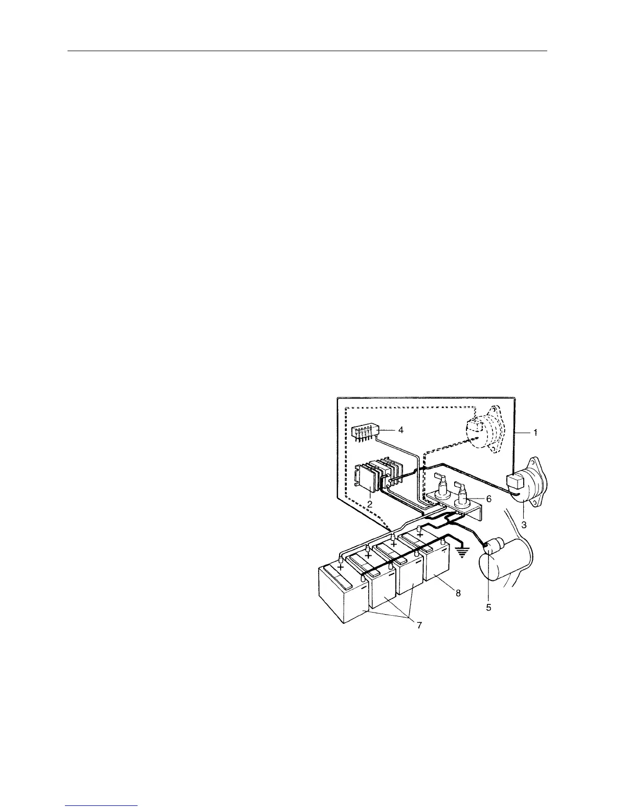
Fig. 112. Connection of sensor system to standard al-
ternator, principle drawing
1.
Sensor conductor (yellow, 1.5 mm
2
,
16 AWG)
2.
Charging distributor (accessory)
3.
Alternator
4.
Fuse panel (accessory)
5.
Starter motor
6.
Main switch
7.
Accessory batteries (accessory)
8.
Start battery (engine)
6 9